Peripherally inserted central venous catheter anti-slip protector
A central venous catheter, anti-slip technology, applied in the direction of catheter, device introduced into the body, drug device, etc., can solve problems such as poor fixation effect of central venous catheter, ensure normality, ensure treatment progress, and prevent tube blockage Effect
- Summary
- Abstract
- Description
- Claims
- Application Information
AI Technical Summary
Problems solved by technology
Method used
Image
Examples
Embodiment 1
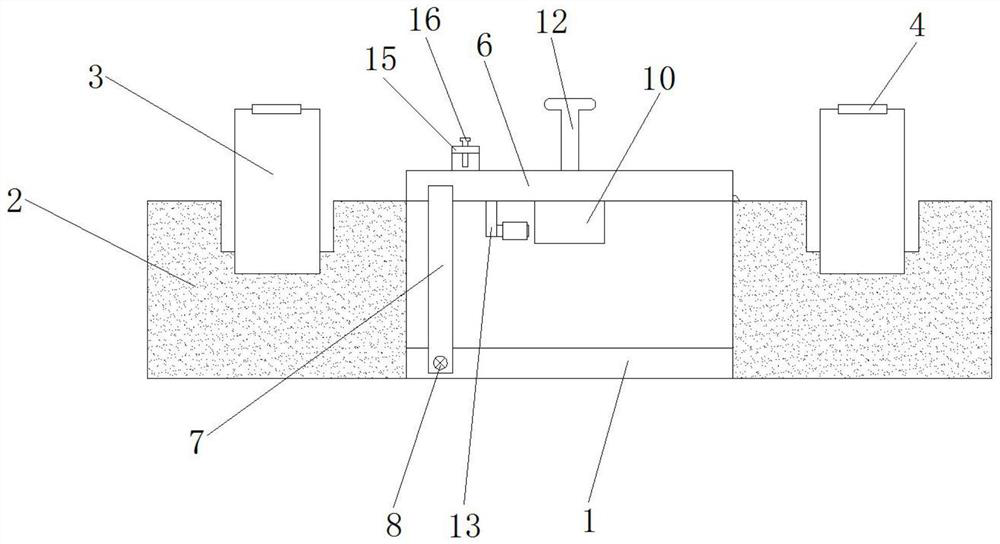
[0026] like figure 1 As shown in the figure, a central venous catheter anti-slip protector is placed in the periphery, including a connecting plate 1, a ferrule 2, a strap 3, a Japanese-shaped buckle 4, a rotating mechanism, a clamping mechanism, a guide groove 5, and a sliding mechanism. The sleeve 2 is fixed on the left and right sides of the connecting plate 1, the strap 3 is fixed on the upper end of the ferrule 2, the sun-shaped buckle 4 is slidably installed on the outside of the strap 3, and the rotating mechanism is rotated on the right On the top of the side ferrule 2 , the clamping mechanism is fixed on the bottom of the rotating mechanism, the guide groove 5 is integrally arranged inside the rotating mechanism, and the sliding mechanism is slidably arranged inside the guide groove 5 .
[0027] The central venous catheter anti-slip protector is placed in the periphery. The medical staff first inserts the patient's arm into the ferrule 2, so as to fit the connecting p...
Embodiment 2
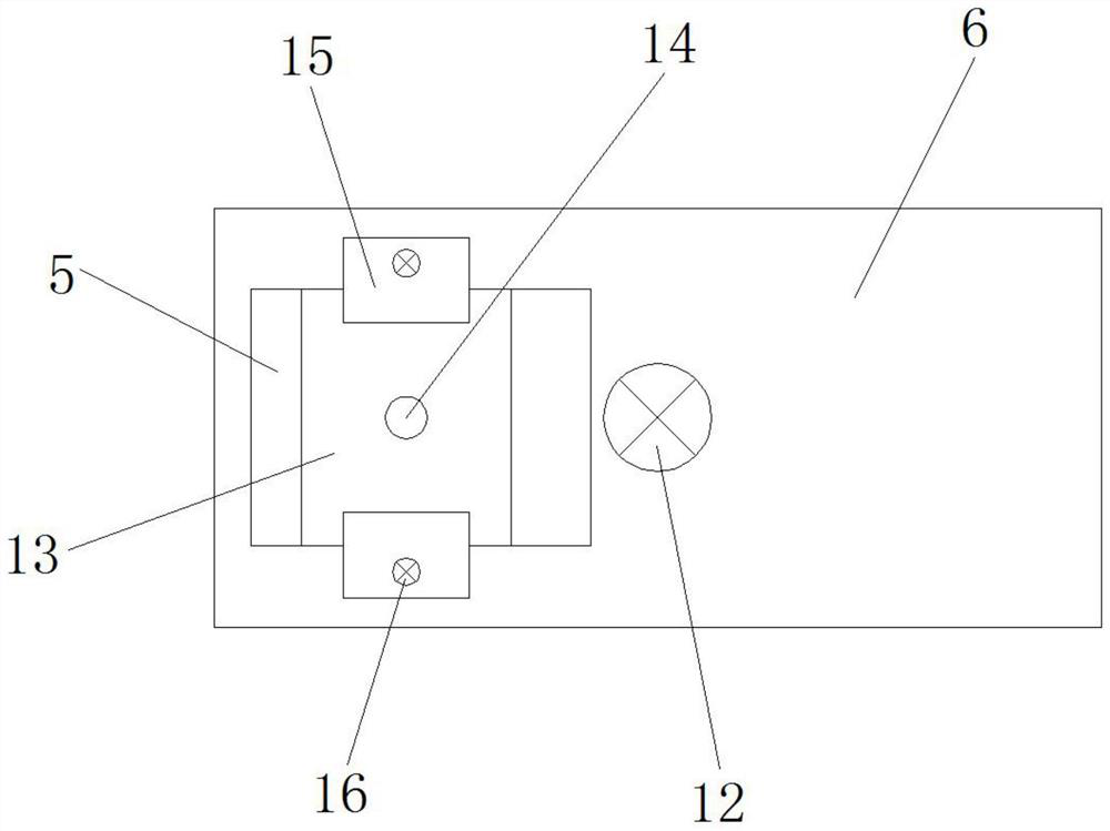
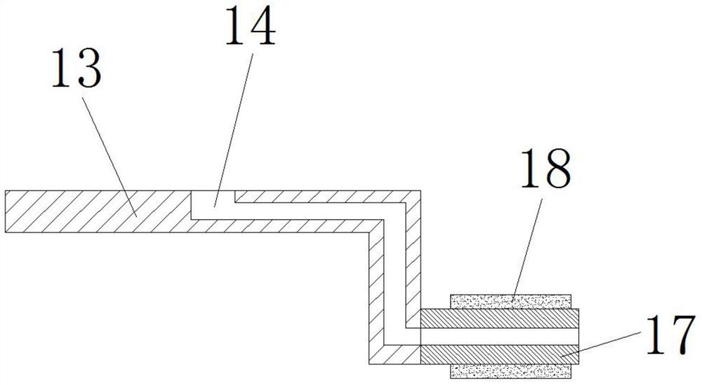
[0029] like figure 1 , figure 2 , image 3 , Figure 4 , Figure 5 , Image 6 As shown in the figure, a central venous catheter anti-slip protector is placed in the periphery, including a connecting plate 1, a ferrule 2, a strap 3, a Japanese-shaped buckle 4, a rotating mechanism, a clamping mechanism, a guide groove 5, and a sliding mechanism. The sleeve 2 is fixed on the left and right sides of the connecting plate 1, the strap 3 is fixed on the upper end of the ferrule 2, the sun-shaped buckle 4 is slidably installed on the outside of the strap 3, and the rotating mechanism is rotated on the right The top of the side ferrule 2, the clamping mechanism is fixed at the bottom of the rotating mechanism, the guide groove 5 is integrally provided inside the rotating mechanism, the sliding mechanism is slidably arranged inside the guide groove 5, and the rotating mechanism The mechanism is composed of a rotating plate 6, an installation strip 7 and a latch 8. The rotating pl...
PUM
 Abstract
Description
Claims
Application Information
 - R&D
- Intellectual Property
- Life Sciences
- Materials
- Tech Scout
- Unparalleled Data Quality
- Higher Quality Content
- 60% Fewer Hallucinations
Browse by: Latest US Patents, China's latest patents, Technical Efficacy Thesaurus, Application Domain, Technology Topic, Popular Technical Reports.
© 2025 PatSnap. All rights reserved.Legal|Privacy policy|Modern Slavery Act Transparency Statement|Sitemap|About US| Contact US: help@patsnap.com


