Automatic bar feeding machine

A feeder and bar material technology, which is applied in the field of automatic bar material feeder, can solve the problems of low efficiency, low safety, and poor overall effect, and achieve the effects of convenient fixing, simple and fast operation, and easy adjustment of the detection position

Pending Publication Date: 2019-12-20
佳亨(浙江)金属科技有限公司
View PDF0 Cites 1 Cited by
  • Summary
  • Abstract
  • Description
  • Claims
  • Application Information

AI Technical Summary

Problems solved by technology

[0002] Many hardware parts used in daily life are partially formed by casting and pressing metal bars in a heated state, and most of the addition of bars one by one requires manual operation, which is inefficient and not safe. not effectively

Method used


Image

  • Automatic bar feeding machine
  • Automatic bar feeding machine
  • Automatic bar feeding machine

Examples


Embodiment Construction

[0036] In order to enable those skilled in the art to better understand the technical solution of this experimental novelty, the preferred embodiments of the present invention are described below in conjunction with specific examples, but it should be understood that these descriptions are only to further illustrate the characteristics and advantages of the present invention, and It is not a limitation on the patent claims of the invention. Based on the embodiments of the present invention, all other embodiments obtained by persons of ordinary skill in the art without making creative efforts belong to the protection scope of the present invention.

[0037] The present invention will be further described below in conjunction with the accompanying drawings and preferred embodiments.

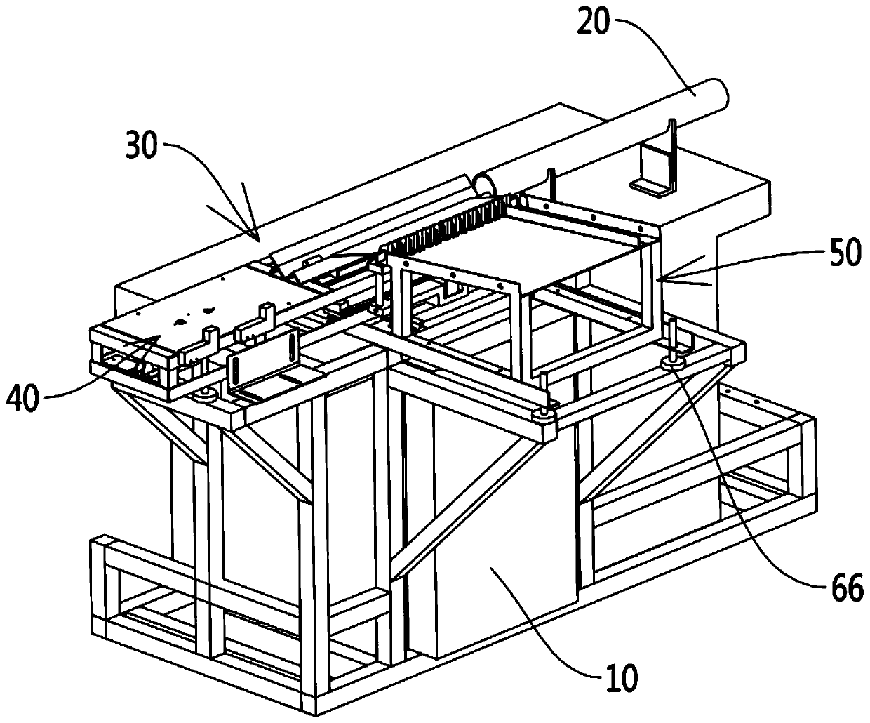
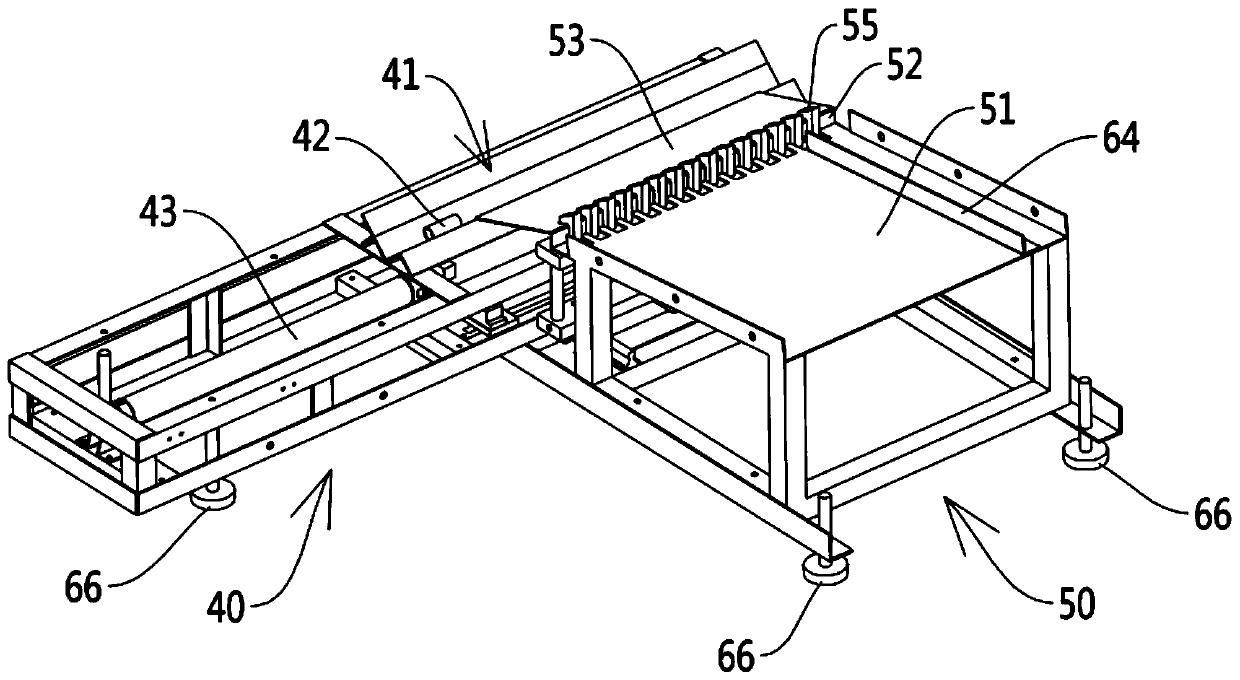
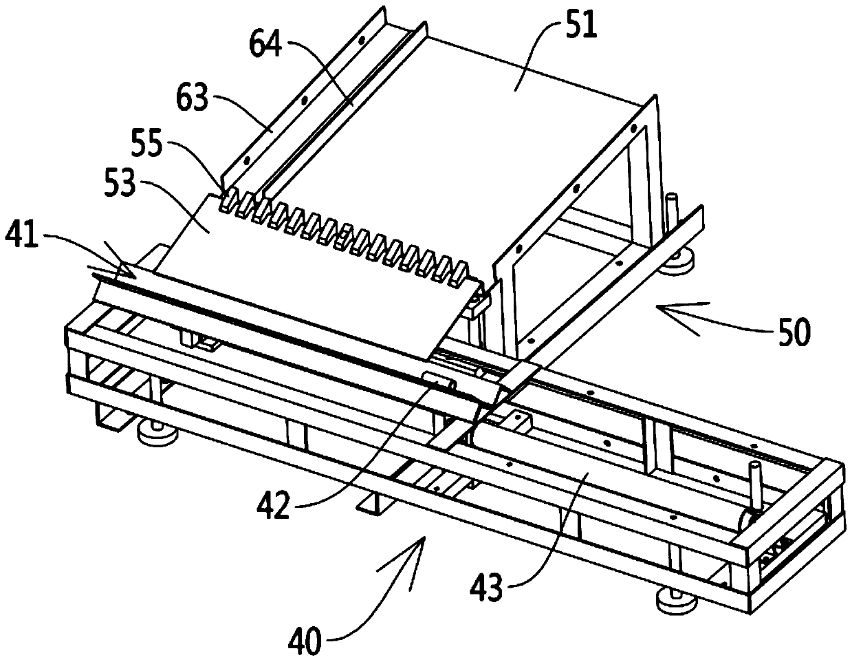
[0038] see Figures 1 to 10 As shown, an automatic bar feeding machine involved in this embodiment includes a machine base 10, on which is provided an intermediate frequency heating tube 20 extend...


PUM


Abstract

The invention discloses an automatic bar feeding machine. The automatic bar feeding machine comprises an engine base. A medium frequency heating pipe is arranged on the engine base. A feeding mechanism is further arranged on the engine base. The feeding mechanism comprises a material pushing assembly and a loading assembly. The material pushing assembly comprises a material groove which shares thesame extension direction with the medium frequency heating pipe. A material pushing block which slides reciprocatingly relative to the material groove is arranged in the material groove. The automatic bar feeding machine further comprises a first push rod cylinder, wherein the first push rod cylinder is connected with the material pushing block, and bars are pushed into the medium frequency heating pipe by the first push rod cylinder. The loading assembly comprises a bar-placing plate which is arranged oblique to the side of the material groove. A bar limiting plate is arranged at the end, close to the material groove, of the bar-placing plate. A bar feeding plate which is also arranged oblique to the side of the material groove is arranged on the bar limiting plate. Lifting holes are formed in the bar-placing plate. Jacking tooth blocks moving up and down are arranged in the lifting holes. The automatic bar feeding machine further comprises a second push rod cylinder which is connected with the jacking tooth blocks and carries the jacking tooth blocks to do up and down movement. The automatic bar feeding machine has the characteristic of automatic loading and can adapt to bars ofdifferent diameters; and the use is flexible and convenient.

Description

technical field [0001] The present invention relates to the field of machinery, more specifically, it relates to an automatic bar feeding machine. Background technique [0002] Many hardware parts used in daily life are partially formed by casting and pressing metal bars in a heated state, and most of the addition of bars one by one requires manual operation, which is inefficient and not safe. not effectively. Accordingly, the present invention proposes an automatic bar feeder. Contents of the invention [0003] The purpose of the present invention is to overcome the shortcomings of the above prior art, and provide an automatic bar feeder, which has the characteristics of automatic feeding, and can adapt to different thickness bars, and is flexible and convenient to use. [0004] In order to solve the above-mentioned technical problems, the object of the present invention is achieved in the following way: an automatic bar feeder related to the present invention includes ...

Claims


Application Information

Patent Timeline
IPC IPC(8): B65G47/82B65G47/74
CPCB65G47/82B65G47/74
Inventor 余波胡华平郭雄伟
Owner 佳亨(浙江)金属科技有限公司
Why Eureka
Try Eureka