Pneumatic vibration cotton feeding box

A cotton box and air pressure technology, used in textiles and papermaking, fiber processing, fiber feeding, etc., can solve the problems of high energy consumption, complex structure, and poor matching effect of rack and pinion pairs.

Pending Publication Date: 2019-12-20
CHANGSHU ZHENTAI NONWOVEN MACHINERY
View PDF4 Cites 2 Cited by
  • Summary
  • Abstract
  • Description
  • Claims
  • Application Information

AI Technical Summary

Problems solved by technology

It is not limited to the cotton feeding box introduced by the above-mentioned exemplified patents, due to the lack of vibration function, the uniformity of the mat cotton output by the paired aforementioned cotton output rollers will be affected to a certain extent.
[0004] CN206927983U recommends "a kind of dual air pressure control cotton feeding box" mentioned in the 3rd to 4th lines of paragraph 0013 of its instruction manual: under the regular vibration of the vibrating grid, the raw cotton in the lower cotton box is produced evenly and c

Method used


Image

  • Pneumatic vibration cotton feeding box
  • Pneumatic vibration cotton feeding box

Examples


Example Embodiment

[0020] In order to be able to understand the technical essence and beneficial effects of the present invention more clearly, the applicant will describe in detail below by way of examples, but the description of the examples is not intended to limit the solution of the present invention. Equivalent transformations that are only formal but not substantial should be regarded as the scope of the technical solutions of the present invention.

[0021] In the following description, all concepts related to the directionality or orientation of up, down, left, right, front and back are for figure 1 The location state is taken as an example, and therefore cannot be understood as a special limitation on the technical solution provided by the present invention.

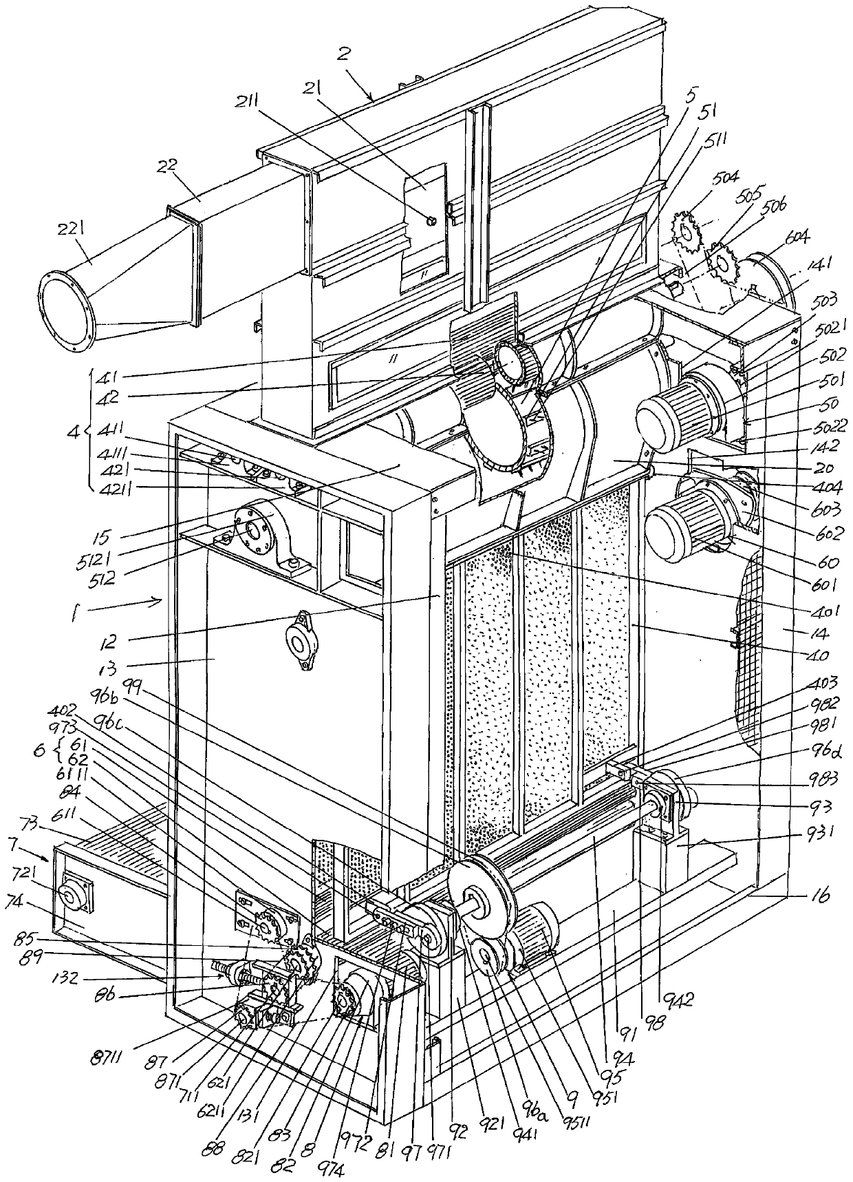
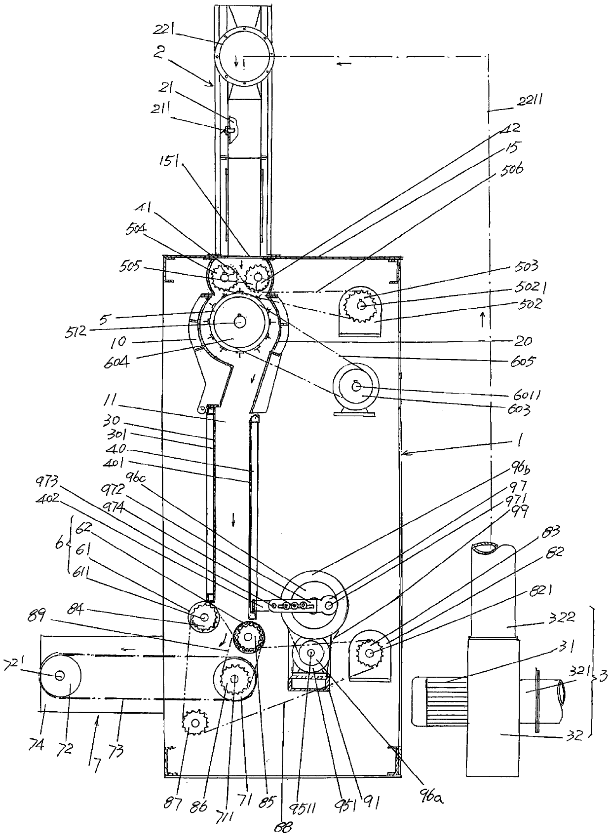
[0022] See figure 1 and figure 2 , showing a cotton box 1, an upper cotton box 2 and a cotton suction mechanism 3 ( figure 2 shown), the upper cotton box 2 is arranged on the top of the lower cotton box 1, the upper cotton b...


PUM


Abstract

Provided is a pneumatic vibration cotton feeding box. The pneumatic vibration cotton feeding box comprises an upper cotton box, a lower cotton box, a cotton suction mechanism, a lower cotton box cotton guiding cavity fiber feeding mechanism, a beater, a fiber feeding roller driving mechanism, a beater driving mechanism, a lower cotton box cotton guiding cavity cotton discharging mechanism, a fiberoutput curtain mechanism and a vibrating plate swinging driving mechanism; a left shield and a right shield are connected to the upper part of the front and rear sides of the lower cotton box; cottonbaffles are positioned in the middles of the front and rear sides of the lower cotton box, the upper end of a vibrating plate is pivoted at the middle part between the front and rear sides of the lower cotton box, and the lower end of the vibrating plate is a free end; the lower cotton box cotton guiding cavity fiber feeding mechanism is supported between the front and rear sides of the lower cotton box; the beater is supported between the front and rear sides of the lower cotton box; the fiber feeding roller driving mechanism and the beater driving mechanism are arranged on the rear side ofthe lower cotton box; the lower cotton box cotton guiding cavity cotton discharging mechanism is supported between the front and rear sides of the lower cotton box; the fiber output curtain mechanismis arranged at the lower part of the lower cotton box; the output curtain driving mechanism is arranged at the lower part of the front side of the lower cotton box; the vibrating plate swinging driving mechanism is arranged at the lower part of the right side of the lower cotton box. The pneumatic vibration cotton feeding box is characterized in that the vibrating plate swinging driving mechanismis connected with the lower part of the vibrating plate in a connection mode based on an eccentric connecting rod, so that the pneumatic vibration cotton feeding box has high adaptability to fibers made of different materials, energy consumption is lowered, and daily inspection and protection workloads are reduced.

Description

technical field [0001] The invention belongs to the technical field of non-woven machinery, and in particular relates to an air pressure vibration cotton feeding box. Background technique [0002] As known in the industry, the aforementioned cotton feeding box is also called the cotton feeding box, which is arranged behind the opener, that is, in the rear of the opener, and is filled with fully opened fibers evenly by means of the action of the cotton conveying fan. The upper cotton box is conveyed and fed to the lower cotton box by paired rollers, and then the fibers are picked up by the corner nail curtain, and the fibers are stripped by the beater into the vibrating chamber, and the vibrating plate is used to form a uniform cotton mat for carding. Machine carding. [0003] The technical information related to the cotton feeding box can be seen in the published Chinese patent literature, such as CN2663451Y (cotton feeding machine with improved structure), CN202492630U (a ...

Claims


Application Information

Patent Timeline
IPC IPC(8): D01G23/00D01G23/08
CPCD01G23/00D01G23/08
Inventor 刘仁才林爱明洪文忠邢伟风李陶生朱轶斌
Owner CHANGSHU ZHENTAI NONWOVEN MACHINERY
Why Eureka
Try Eureka