Grab bucket system and engineering vehicle

A technology for grabs and counterweights, applied in earth movers/excavators, construction, etc., can solve the problems of reducing fuel utilization, reducing the lifting and lowering speed of the grab, and increasing the lifting and lowering resistance of the grab body , to achieve the effect of improving fuel utilization and avoiding lowering resistance

Pending Publication Date: 2019-12-20
XUZHOU XUGONG FOUND CONSTR MACHINERY
0 Cites 1 Cited by

AI-Extracted Technical Summary

Problems solved by technology

[0002] Due to the fixed weight of the existing ordinary grab, its fuel consumption cannot be changed according to the requirements of the working conditions, which reduces the utilization rate of fuel, and the counterweight is installed inside the grab body, which will ...

Method used

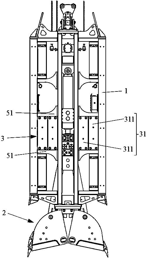
As shown in Fig. 1a and Fig. 1b, present embodiment 1 provides a kind of grab bucket system, comprises grab bucket body 1, bucket head assembly 2 and counterweight block assembly 3; Bucket head assembly 2 is positioned at grab Below the bucket body 1, the counterweight block assembly 3 is installed outside the grab bucket body 1 to adjust the weight of the grab bucket body 1, thereby changing the digging capacity of the bucket head assembly 2, and not affecting the backflow channel of the mud.
In summary, the grab system sets the counterweight assembly on the outside of the grab body, which can adjust the excavation capacity of the bucket head assembly, and does not affect the anti-flush channel of the mud, effectively avoiding the impact of the mud on the The lifting/lowering resistance of the grab body improves the fuel utilization rate and meets the high requirements of fuel economy and environmental protection; by symmetrically distributing several counterweights on the outside of the grab body, the number can also be adjusted according to the working conditions to adjust the flexibility At the same time, the verticality of the grab body can be guaranteed, so as to prevent the tilt of the grab body from affecting the normal use of the grab system; by setting the counterweight position for installing each counterweight, the installation stability of the counterweight can be guaranteed , thereby improving the mechanical stability of the entire grab system.
In the grab system of the p...

Abstract

The invention discloses a grab bucket system and an engineering vehicle. The grab bucket system comprises a grab bucket body, a bucket head assembly and a balancing weight assembly; the bucket head assembly is mounted below the grab bucket body, the balancing weight assembly is mounted on the outer side of the grab bucket body, the balancing weight assembly comprises a balancing weight set, the balancing weight set is connected with the grab bucket body through a balancing weight position, the balancing weights in the balancing weight set are detachably connected, the balancing weights are added and decreased according to the working condition, and the weight of the grab bucket body is adjusted. According to the grab bucket system, the balancing weight assembly is arranged on the outer side of the grab bucket body, and is used for adjusting the weight of the grab bucket body, the excavating capacity of the bucket head assembly is adjusted, an anti-surging channel of slurry is not affected, lifting and descending resistance of slurry to the grab bucket body is effectively avoided, the fuel oil use rate is improved, and the fuel economy and environment-friendly high needs can be met.

Application Domain

Soil-shifting machines/dredgers

Technology Topic

Automotive engineeringFuel oil +1

Image

  • Grab bucket system and engineering vehicle
  • Grab bucket system and engineering vehicle
  • Grab bucket system and engineering vehicle

Examples

  • Experimental program(1)

Example Embodiment

[0029] In order to make the objectives, technical solutions and advantages of the present invention clearer, the technical solutions in the embodiments of the present invention will be described in more detail below with reference to the accompanying drawings in the embodiments of the present invention. Throughout the drawings, the same or similar reference numbers refer to the same or similar elements or elements having the same or similar functions. The described embodiments are some, but not all, of the embodiments of the present invention. The embodiments described below with reference to the accompanying drawings are exemplary, and are intended to explain the present invention and should not be construed as limiting the present invention. Based on the embodiments of the present invention, all other embodiments obtained by those of ordinary skill in the art without creative efforts shall fall within the protection scope of the present invention. The embodiments of the present invention will be described in detail below with reference to the accompanying drawings.
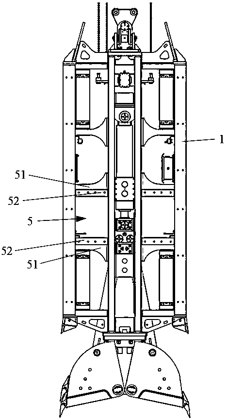
[0030] like Figure 1a and Figure 1b As shown, Embodiment 1 provides a grab bucket system, including a grab bucket body 1, a bucket head assembly 2 and a counterweight block assembly 3; the bucket head assembly 2 is located below the grab bucket body 1, and the counterweight block assembly The components 3 are installed on the outside of the grab bucket body 1 to adjust the weight of the grab bucket body 1, thereby changing the digging capacity of the bucket head assembly 2 and not affecting the backflow channel of the mud.
[0031] In the grab bucket system of the present embodiment 1, the counterweight block assembly 3 is arranged on the outside of the grab bucket body 1, which can not only adjust the digging capacity of the bucket head assembly, but also does not affect the backflow channel of the mud, which effectively avoids the impact of mud on the grab bucket. The lifting/lowering resistance of the body improves the fuel utilization rate and meets the high requirements of fuel economy and environmental protection.
[0032] As an optional implementation of a counterweight assembly.
[0033] See Figure 1a , the counterweight block assembly 3 includes: counterweight block groups 31 distributed on the outside of the grab body 1 ; each counterweight block group 31 includes at least two counterweight blocks 311 arranged side by side. because Figure 1a Only the main view of the grapple system is shown, so the other two weight groups are blocked and cannot be displayed.
[0034] The counterweight block assembly 3 of this embodiment adjusts the weight of the grab bucket body through the counterweight blocks symmetrically distributed on the outer side of the grab bucket body 1, which will not affect the backflow channel of the mud, and the number of counterweight blocks 311 can also be adjusted according to the working conditions. (such as geological conditions, mud viscosity, etc.) adjustment, high flexibility, and symmetrical distribution of counterweights, can also ensure the verticality of the grab body, so as not to affect the normal use of the grab system due to the inclination of the grab body.
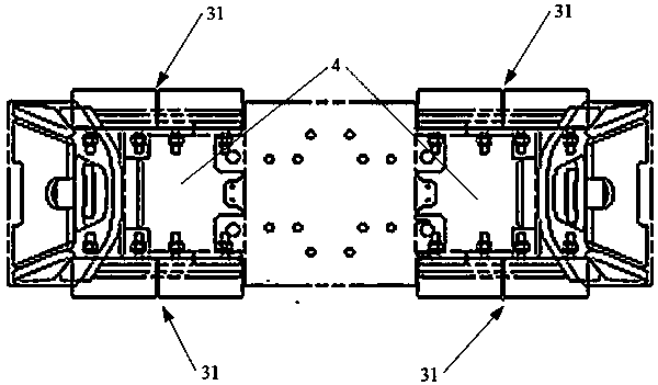
[0035] Further, see Figure 1a and figure 2 , the grab bucket system also includes two mud passages 4 arranged in the middle of the grab bucket body 1 , and four counterweight positions 5 symmetrically distributed on both sides of the mud passage 4 .
[0036] An optional embodiment as a counterweight.
[0037] See Figure 1b , the counterweight position 5 includes two beams 51 arranged up and down on the grab body 1 and a fixed plate 52 respectively located on the outer side of each beam 51 .
[0038] The corresponding counterweight block groups 31 are suitable for installation between the outer sides of the two beams 51 and the two fixing plates 52 . Each counterweight position 5 is set in a one-to-one correspondence with the counterweight block group 31, that is, two counterweight blocks 311 can be installed side by side on one counterweight position 5, which can ensure the installation stability of the counterweight block and can also flexibly select the counterweight block. quantity.
[0039] When installing the counterweight, try to keep the position of the counterweight as symmetrical as possible to ensure the stability and verticality of the grab body. Two; for another example, when four counterweight groups 31 are selected for the grab system, one counterweight can be installed on each counterweight position; for example, when six counterweight groups 31 are selected for the grab system, the inclined block can be selected. The number of counterweights installed in the diagonal counterweight positions is the same.
[0040] Optionally, the counterweight 311 is adapted to be fastened to the fixing plate 52 by bolts.
[0041] Optionally, the fixing plate 52 is connected to the grab body 1 by welding.
[0042] To sum up, in this grab bucket system, the counterweight block assembly is arranged on the outside of the grab bucket body, which can not only adjust the digging capacity of the bucket head assembly, but also does not affect the backflow channel of the mud, which effectively avoids the impact of mud on the grab bucket body. The lifting/lowering resistance improves the fuel utilization rate and meets the high requirements of fuel economy and environmental protection; by symmetrically distributing a number of counterweights on the outside of the grab body, the number of counterweights can also be adjusted according to the working conditions, and the adjustment flexibility is high. At the same time, the verticality of the grab body can also be ensured, so as to prevent the inclination of the grab body from affecting the normal use of the grab system; by setting the counterweight position for installing each counterweight block, the installation stability of the counterweight block can be ensured, thereby improving the Mechanical stability of the entire grapple system.
[0043] The present invention also provides an engineering vehicle, including the above-mentioned grab system.
[0044] Here, it should be further noted that, due to the fixed weight of the existing ordinary grab, its fuel consumption cannot be changed with the requirements of the working conditions, which reduces the utilization rate of fuel, and the counterweight is installed inside the grab body (such as Figure 4 The position referred to in the middle A), the backflow channel of the mud will be blocked. The solution in this application document is that the counterweight blocks in the counterweight block group are connected in a detachable manner, and the counterweight block assembly is installed on the outside of the grab body (such as Figure 4 the position referred to at B).
[0045] Finally it should be noted that: the above embodiment is only used to illustrate the technical scheme of the present invention and not to limit it; Although the present invention has been described in detail with reference to the preferred embodiment, those of ordinary skill in the art should understand: The specific embodiments of the invention are modified or some technical features are equivalently replaced; without departing from the spirit of the technical solutions of the present invention, all of them should be included in the scope of the technical solutions claimed in the present invention.

PUM

no PUM

Description & Claims & Application Information

We can also present the details of the Description, Claims and Application information to help users get a comprehensive understanding of the technical details of the patent, such as background art, summary of invention, brief description of drawings, description of embodiments, and other original content. On the other hand, users can also determine the specific scope of protection of the technology through the list of claims; as well as understand the changes in the life cycle of the technology with the presentation of the patent timeline. Login to view more.

Similar technology patents

Correction method for sea wave resistance in evaluation of ship performance

ActiveCN110852619Areliable evaluation curveimprove fuel efficiency
Owner:SHANDONG JIAOTONG UNIV

Method and system to improve atomization and combustion of heavy fuel oils

InactiveUS20150122216A1improve fuel efficiencyimprove combustion process
Owner:HELPFUL TECH

Azole ionic liquid containing phosphine compound and preparation method thereof

InactiveCN110746460AImprove fuel efficiencyhigh energy barrier
Owner:INST OF CHEM MATERIAL CHINA ACADEMY OF ENG PHYSICS

Classification and recommendation of technical efficacy words

  • Improve fuel efficiency

Power configuration system for fuel cell hybrid vehicle and method for controlling the same

ActiveUS20100089672A1regeneration amount be increaseimprove fuel efficiency
Owner:HYUNDAI MOTOR CO LTD

Aerodynamic drag reduction systems

InactiveUS20070187990A1reduce aerodynamic dragimprove fuel efficiency
Owner:SHAHBAZI KHOSROW

Speed control method for working vehicle

ActiveUS20050282682A1improve fuel efficiency
Owner:KANZAKI KOKYUKOKI MFG
Why Eureka
Try Eureka