
Method for indirectly evaluating safety condition of existing pipeline under shield tunneling

A safety and pipeline technology, applied in earthwork drilling, special data processing applications, instruments, etc., can solve problems such as labor-intensive, large error, time-consuming and labor-intensive measurement, and achieve the effect of reducing monitoring workload and monitoring difficulty.

Active Publication Date: 2019-12-20
SHANGHAI CONSTRUCTION GROUP
View PDF5 Cites 0 Cited by
  • Summary
  • Abstract
  • Description
  • Claims
  • Application Information

AI Technical Summary

Problems solved by technology

[0003] First, for larger pipe diameters, it is possible to manually enter the pipeline to install sensors for monitoring. This method is relatively labor-intensive. For some pressure pipelines such as water supply, sewerage, and gas, manual installation of sensors is extremely risky;
[0004] Second, for pipes with small diameters, insert a long probe from the ground to the location of the pipe, and measure the settlement of the surrounding soil to approximate the settlement of the pipe. Although this method is also an indirect method, the measured data is not the deformation of the pipe. data, the error is relatively large, and the measurement is time-consuming and laborious

Method used


Image

  • Method for indirectly evaluating safety condition of existing pipeline under shield tunneling
  • Method for indirectly evaluating safety condition of existing pipeline under shield tunneling
  • Method for indirectly evaluating safety condition of existing pipeline under shield tunneling

Examples


Embodiment 1

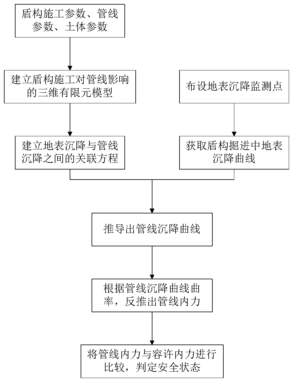
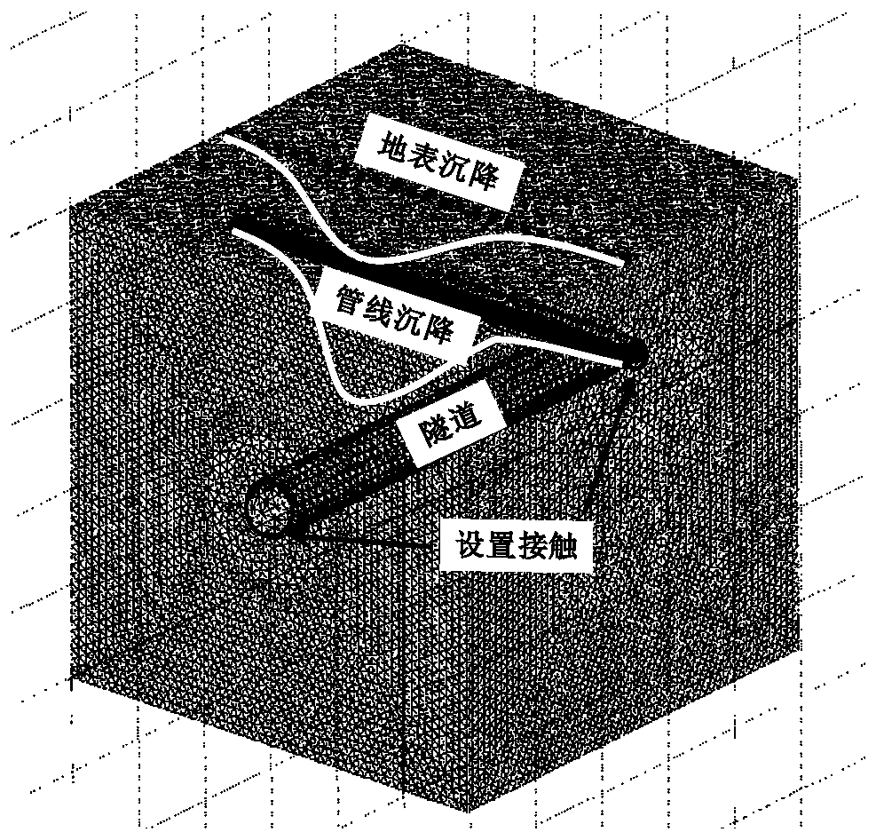
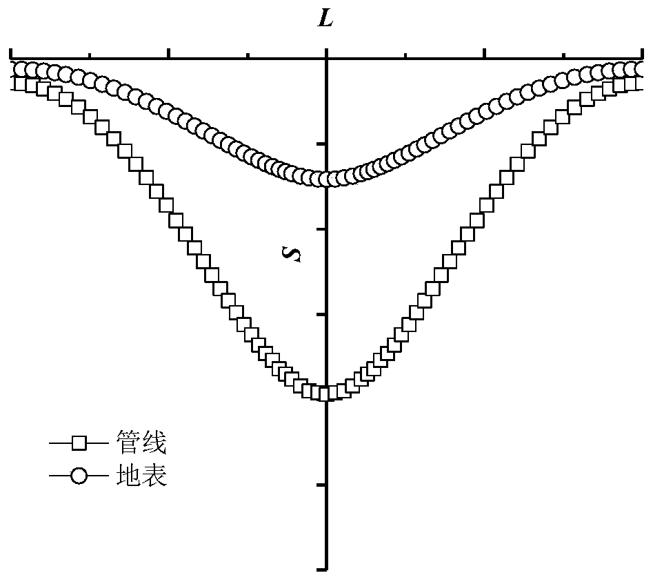
[0028] Combine below Figure 1 to Figure 3 , detailing the structural composition of the method for indirectly evaluating the safety behavior of existing pipelines under shield tunneling in the present invention.

[0029] Please refer to Figure 1 to Figure 3 , a method for indirectly evaluating the safety behavior of existing pipelines under shield tunneling, the method includes the following steps:

[0030] Step S1: According to engineering data, obtain shield construction parameters, existing pipeline parameters and soil parameters;

[0031] Step S2: Based on the parameters obtained in step S1, numerical software is used to simulate the shield tunneling through pipeline construction;

[0032] Step S3: Extract the surface settlement and pipeline settlement curves in the numerical simulation, wherein L represents the distance extending from the midline of the shield section to the horizontal ends, and S represents the vertical deformation of the ground surface and the pipel...


PUM


Abstract

The invention provides a method for indirectly evaluating safety condition of an existing pipeline under shield tunneling and belongs to the technical field of shield construction environment influences. Correlation between pipeline settlement and ground surface settlement is built, so that it is achieved that the safety condition of a pipeline can be adjudged by monitoring the ground surface settlement. According to method, firstly, shield construction parameters, pipeline parameters and soil body parameters are combined, a correlation equation between ground surface settlement and pipeline settlement is built through a three-dimensional finite element model; meanwhile, ground surface settlement monitoring points are arranged, and a ground surface settlement curve in shield tunneling is acquired; then a pipeline settlement curve is deduced; then according to the curvature of the pipeline settlement curve, the pipeline inner force is reversely deduced; and finally, the pipeline inner force is compared with allowed inner force, the safety state is judged. According to the method, it is not needed to directly monitor the pipeline, the correlation between ground surface settlement andpipeline settlement is built, so that it is achieved that the safety condition of the pipeline can be adjudged by monitoring ground surface settlement data, and the monitoring workload and the monitoring difficulty in engineering are greatly reduced.

Description

technical field [0001] The invention relates to the technical field of environmental impact of shield tunneling, in particular to a method for indirect evaluation of the safety behavior of existing pipelines under shield tunneling. Background technique [0002] The existing underground pipeline deformation monitoring mainly consists of the following methods: [0003] First, for larger pipe diameters, it is possible to manually enter the pipeline to install sensors for monitoring. This method is relatively labor-intensive. For some pressure pipelines such as water supply, sewerage, and gas, manual installation of sensors is extremely risky; [0004] Second, for pipes with small diameters, insert a long probe from the ground to the location of the pipe, and measure the settlement of the surrounding soil to approximate the settlement of the pipe. Although this method is also an indirect method, the measured data is not the deformation of the pipe. Data, the error is relatively...

Claims


Application Information

Patent Timeline
IPC IPC(8): E21D9/06G06F17/50
CPCE21D9/06
Inventor 沈雯沈蓉孙廉威王新新程子聪
Owner SHANGHAI CONSTRUCTION GROUP
Learn More