Supercharge Your Innovation With Domain-Expert AI Agents!

Novel oilfield sewage tank oil receiving control device and method

A technology for oilfield sewage and control devices, which is applied to chemical instruments and methods, grease/oily substance/suspton removal devices, valve devices, etc. It can solve the problem of not being able to see clearly the extent to which the control valve is controlled, not being able to observe and remove it, and not using it properly. Convenience and other issues, to achieve the effect of good use, fast speed, accurate control of oil collection

Inactive Publication Date: 2019-12-20
赵春海
View PDF9 Cites 0 Cited by
  • Summary
  • Abstract
  • Description
  • Claims
  • Application Information

AI Technical Summary

Problems solved by technology

[0002] The oil collection control of the existing oil field sewage tanks is realized through the control valve. Although the control valve can control the oil collection degree of the oil field sewage tank, it is impossible to see the extent to which the control valve is controlled, and it cannot be observed and cleared, which is inconvenient to use.

Method used


Image

  • Novel oilfield sewage tank oil receiving control device and method
  • Novel oilfield sewage tank oil receiving control device and method

Examples


Embodiment 1

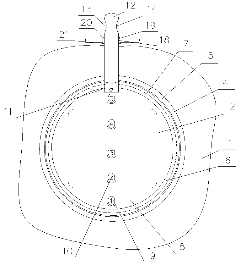
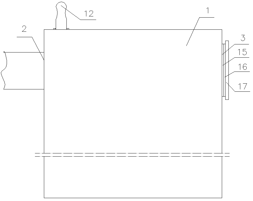
[0019] A novel oil collection control device for oil field sewage tanks, comprising: an oil field sewage tank 1, the oil field sewage tank has an oil inlet 2, and the oil field sewage tank has an observation port 3, the observation port is connected to the Corresponding to the oil inlet, the area of ​​the oil inlet is greater than the area of ​​the observation port, the oil inlet is welded to connect the ring plate 4, the ring plate is welded to the vertical ring plate 5, the The vertical ring plate is welded with the fixed ring 6, and the upper half of the vertical ring plate is provided with a semicircular through groove 7, and the valve plate 8 is tightly fitted between the oil field sewage tank and the fixed ring, and the described The valve plate is connected with a group of lamps 9, and the lamps are connected with a switch and a power supply. Several numbers 10 of 1-10 are written on the lamps, and the numbers are red.

[0020] The area of ​​the oil inlet is larger than...

Embodiment 2

[0023] In the new oil collection control device for oilfield sewage tanks described in Example 1, the ring plate and the vertical ring plate are located at the periphery of the oil inlet, and the top of the valve plate is clamped by an inverted U-shaped clip Holder 11, said inverted U-shaped clamping piece is riveted and fixed to the top of said valve plate, said inverted U-shaped clamping piece is relative to said valve plate and does not rotate, said inverted U-shaped clamping piece The handle 12 is welded on the top of the shaped clamp, and the handle has a left groove 13 and a right groove 14, and the left groove is opposite to the right groove.

[0024] The handle is connected to the valve plate through an inverted U-shaped clamping piece. After riveting, the handle and the valve plate will not shake, which provides the necessary guarantee for the adjustment of the valve plate.

Embodiment 3

[0026] In the novel oil collection control device for oil field sewage tank described in Embodiment 1, the outer side of the observation port is bonded with a fixed magnetic ring 15, and the fixed magnetic ring is attracted to the outer magnetic ring 16, and the outer magnetic ring is bonded Transparent plate 17.


PUM


Abstract

The invention discloses a novel oilfield sewage tank oil receiving control device and method. The novel oilfield sewage tank oil receiving control device comprises an oilfield sewage tank, the oilfield sewage tank is provided with an oil inlet and a viewing port, the viewing port corresponds to the oil inlet, and the area of the oil inlet is larger than that of the viewing port; a ring plate is inwelding connection with the oil inlet, a vertical ring plate is welded to the ring plate, a fixed ring is welded to the vertical ring plate, and the upper half part of the vertical ring plate is provided with a semi-circular through groove; a valve plate is inserted between the oilfield sewage tank and the fixed ring in a close matching mode; and a lamp is connected with the valve plate, severalnumbers of 1-10 are written on the lamp, and the numbers are red. The oilfield sewage tank oil receiving control device is provided.

Description

Technical field: [0001] The invention relates to a novel oil collection control device and method for sewage tanks in oil fields. Background technique: [0002] The oil collection control of the existing oilfield sewage tanks is realized by the control valve. Although the control valve can control the oil collection degree of the oilfield sewage tank, it is impossible to see the extent of the control valve, and it is impossible to observe and clear it, which is inconvenient to use. Invention content: [0003] The purpose of the present invention is to provide a novel oil collection control device and method for oil field sewage tanks that can clearly see the effect of oil control and has good use effect. [0004] Above-mentioned purpose realizes by following technical scheme: [0005] A novel oil collection control device for oil field sewage tanks, comprising: an oil field sewage tank, the oil field sewage tank has an oil inlet, the oil field sewage tank has an observati...

Claims


Application Information

Patent Timeline
IPC IPC(8): F16K3/02F16K3/30F16K31/60F16K37/00B01D17/032C02F1/40
CPCF16K3/0281F16K3/30F16K31/60F16K37/0041B01D17/02C02F1/40
Inventor 赵春海丁超李海波陈红超荣远宏朴明珠孙家晖梁涛任法德李旭东
Owner 赵春海
Features
  • R&D
  • Intellectual Property
  • Life Sciences
  • Materials
  • Tech Scout
  • Unparalleled Data Quality
  • Higher Quality Content
  • 60% Fewer Hallucinations
Learn More