A device and method for measuring spatial displacement and strain based on CCD camera

A space displacement and strain measurement technology, applied in the field of optical measurement, can solve the problems of high operation complexity, high cost and large volume of laser rangefinders, and achieve the effects of accurate calculation results, compact optical path structure and flexible application

Active Publication Date: 2022-03-25
GUANGZHOU UNIVERSITY
View PDF6 Cites 0 Cited by
  • Summary
  • Abstract
  • Description
  • Claims
  • Application Information

AI Technical Summary

Problems solved by technology

Traditional spatial digital image correlation requires two CCD cameras, which not only makes the hardware cost high, but also provides a synchronous trigger device in order to realize the simultaneous operation of the two cameras, which makes the operation more complex
[0003] At present, the invention patent with the publication number CN103940357A discloses a non-contact spatial displacement measuring device, which includes a laser range finder arranged at the reference point, an imaging transparent plate arranged at the detection point, and an imaging transparent plate arranged on the imaging transparent plate. For the image acquisition device, drive module, and control module on the side of the laser rangefinder, the above-mentioned measuring device has the following disadvantages: 1. The laser rangefinder is expensive, bulky, and inconvenient to carry; 2. There is only one optical path to the sensor during shooting , which may result in missing reference point information

Method used


Image

  • A device and method for measuring spatial displacement and strain based on CCD camera
  • A device and method for measuring spatial displacement and strain based on CCD camera
  • A device and method for measuring spatial displacement and strain based on CCD camera

Examples


Embodiment Construction

[0039] The present invention will be further described below in conjunction with the accompanying drawings and embodiments.

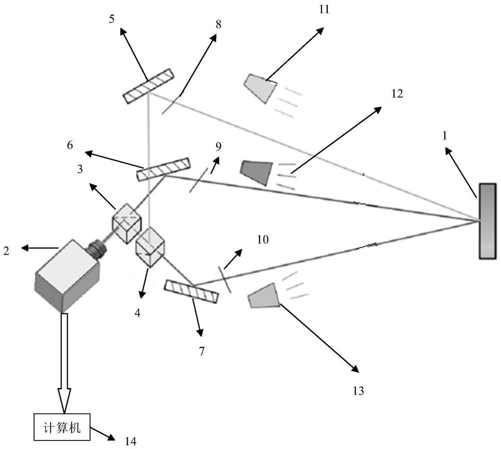
[0040] figure 1 Shown is a structural diagram of a specific example of the present invention. The shape of the surface of the measured object 1 in the present invention does not affect the application of the present invention, no matter it is a plane or a curved surface, it can be measured by the present invention.

[0041] figure 1 Among them, a spatial displacement and strain measurement device based on a CCD camera, including a CCD color camera 2, a first beam splitter 3, a second beam splitter 4, a first mirror 5, a second mirror 6, and a third mirror 7 The above-mentioned first reflector 5, the first beam splitter 3 and the second beam splitter 4 form the first optical path; the second reflector 6 and the first beam splitter 3 form the second optical path; the third reflector 7, The second beam splitter 4 and the first reflection mirror 5 form t...


PUM


Abstract

The invention discloses a spatial displacement and strain measurement device and method based on a CCD camera, comprising a CCD color camera, a first beam splitter, a second beam splitter, a first reflector, a second reflector, and a third reflector; The first reflector, the first beam splitter and the second beam splitter form the first light path, the second reflector and the first beam splitter form the second light path, and the third reflector, the second beam splitter and the first beam splitter The beam splitter forms the third light path; the first light path, the second light path and the third light path all enter the CCD color camera; the CCD color camera is used to pass through the first light path, the second light path and the third light path shoot. The device of the present invention has a simple structure and does not need any synchronous trigger device to realize synchronous data acquisition, which is equivalent to using three CCD cameras to shoot from three directions, making the calculation results more accurate, and the present invention has no influence on the shape of the surface of the measured object. Restricted, flexible application.

Description

technical field [0001] The invention relates to the field of optical measurement, in particular to a CCD camera-based spatial displacement and strain measurement device and method. Background technique [0002] Since the advent of the digital image correlation method in 1980, the method has been developed rapidly. In order to measure spatial displacement and strain, some scholars have proposed a spatial digital image correlation method. This method has many advantages, such as: full field, high precision, non-contact and insensitivity to the measurement environment, etc., which makes this method applied in many fields of displacement and strain measurement. The traditional spatial digital image correlation requires two CCD cameras, which not only makes the hardware cost high, but also needs to provide a synchronous trigger device in order to realize the simultaneous operation of the two cameras, which makes the operation more complex. [0003] At present, the invention pat...

Claims


Application Information

Patent Timeline
Patent Type & Authority Patents(China)
IPC IPC(8): G01B11/02G01B11/16
CPCG01B11/02G01B11/16
Inventor 蔡长青黄永辉陈慧敏
Owner GUANGZHOU UNIVERSITY
Why Eureka
Try Eureka