Simulation device for thermal environment of supersonic/subsonic combustion of combined engine

An analog device, subsonic technology

Active Publication Date: 2020-06-30
NORTHWESTERN POLYTECHNICAL UNIV
View PDF8 Cites 0 Cited by
  • Summary
  • Abstract
  • Description
  • Claims
  • Application Information

AI Technical Summary

Problems solved by technology

Therefore, it is still difficult to design a heating simulation device that can work for a long time and easily simulate sub / supersonic speed, which has caused great limitations for fully carrying out the simulation of the thermal environment and the verification of the thermal protection scheme.

Method used


Image

  • Simulation device for thermal environment of supersonic/subsonic combustion of combined engine
  • Simulation device for thermal environment of supersonic/subsonic combustion of combined engine
  • Simulation device for thermal environment of supersonic/subsonic combustion of combined engine

Examples


Embodiment Construction

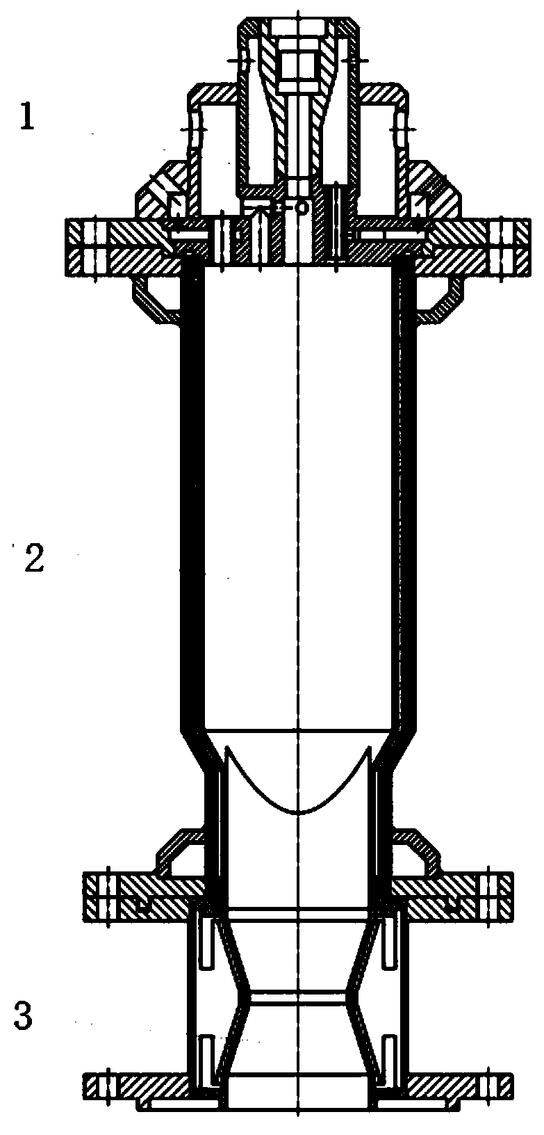
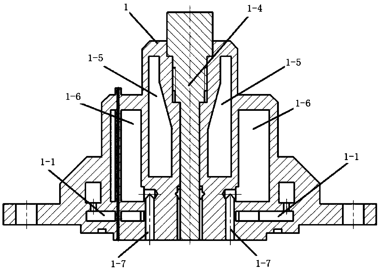
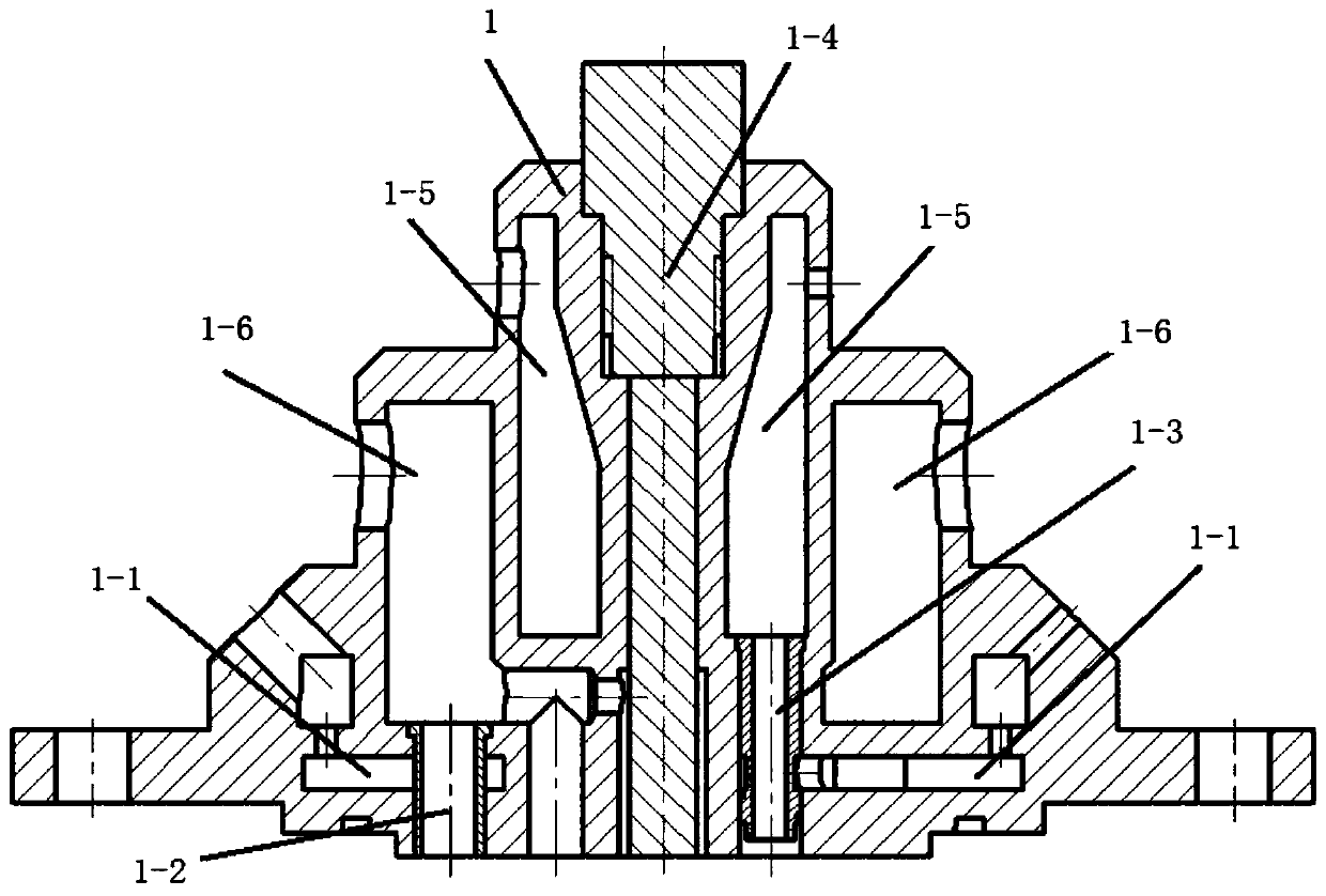
[0033] The present invention is a combination engine super / subsonic combustion thermal environment simulation device, such as figure 1 As shown, the injector 1 and the combustion chamber 2 are connected up and down; the body of the combustion chamber 2 adopts a welded structure of the inner liner and the shell, and a cooling channel is formed between the two. The cooling water inlet is located at the lower part of the combustion chamber, and the cooling water The outlet is positioned at the head position on the top, and the body of the combustion chamber 2 is cylindrical. Along the central axis of the injector 1, there is a central cavity with upper and lower openings, which communicates with the combustion chamber 2. An electric spark igniter 1-4 is arranged axially in the central cavity; the inner diameter of the central cavity is slightly larger than that of the electric spark ignition The diameter of the cylindrical rods of devices 1-4 is such that there is a gap between t...


PUM


Abstract

The invention discloses a simulation device of composite engine supersonic / subsonic combustion heat environment. The simulation device comprises an injector and a combustion chamber which are connected up and down and communicated; a center cavity with an opened upper side and an opened lower side is formed along with an axle wire of the injector in a penetrating manner, the center cavity is communicated with the combustion chamber, an electric spark igniter is axially arranged in the center cavity; the injector is a three-cavity structure, the three-cavity structure are an oxygen cavity, an air cavity and an alcohol cavity; each cavity is revolved body-shaped, wherein the oxygen cavity surrounds the center cavity, the air cavity surrounds the outside of the oxygen cavity, and the alcoholcavity is located at the lower part of the oxygen cavity; the bottoms of the oxygen cavity, the air cavity and the alcohol cavity are communicated with the combustion chamber to inject the corresponding oxygen, air and alcohol into the combustion chamber. The simulation device can realize the realize reliable injection panel thermal protection, thereby effectively supporting the design of the thermal protection scheme of the engine.

Description

technical field [0001] The invention belongs to the technical field of rocket ramjet combined engines, and in particular relates to a simulation device for the super / subsonic combustion heat environment of combined engines. Background technique [0002] The rocket ramjet combined power engine integrates the rocket engine and the air-breathing ramjet in the same flow channel, combining the advantages of the high thrust-to-weight ratio of the rocket engine and the high specific impulse of the air-breathing ramjet, and can work in a wide range of Mach numbers , is considered to be one of the main power systems of the next generation of aerospace vehicles. [0003] The rocket ramjet combined engine has a wide range of operating speed and airspace, and it often needs to work in different combustion modes to obtain the best overall performance under different incoming flow conditions. The distribution and conditions of combustion heat release under different working modes are sig...

Claims


Application Information

Patent Timeline
Patent Type & Authority Patents(China)
IPC IPC(8): G01M15/14
CPCG01M15/14
Inventor 朱韶华王亚军秦飞魏祥庚张铎叶进颖
Owner NORTHWESTERN POLYTECHNICAL UNIV
Why Eureka
Try Eureka