Plane installation structure and installation method of control cabinet in GIS combined electrical apparatus

A technology for combining electrical appliances and installation structures, which is applied to substations/switchgear boards/panels/desks, switchgears, electrical components, etc., and can solve the problem of excessive distance between components and terminals on the panel, increased redundancy, and cabinet structure Complicated problems, to achieve the effect of simple and clear wiring in the cabinet, reducing the cost of wires, and improving assembly efficiency

Pending Publication Date: 2019-12-20
上海西电高压开关有限公司
View PDF11 Cites 0 Cited by
  • Summary
  • Abstract
  • Description
  • Claims
  • Application Information

AI Technical Summary

Problems solved by technology

[0002] At present, the structure of the mainstream control cabinet in China is mainly three-dimensional arrangement, and the components on the panel and the terminals in the cabinet are mostly not on the same plane. Although this design can install various components, the disadvantages are obvious: 1. The excessive distance between components and terminals causes a lot of waste of wires, and the complex structure makes the calculation of wire length inaccurate, which increases a lot of redundancy; 2. Wiring workers need to drill from the back of the cabinet to wire in the cabinet. Limitation, not only reduces the efficiency of wiring, but also affects the physical and mental health of workers
The disadvantages of the other frame structure are: 1. The components installed on the door panel and the components in the cabinet need to be installed separately, and the wiring efficiency is not high; 2. The wires between the components on the door panel and the components in the cabinet can only be connected by the door. The wiring on the shaft side, the wiring method is single and the length of the wire is not easy to control, resulting in waste of wires

Method used


Image

  • Plane installation structure and installation method of control cabinet in GIS combined electrical apparatus
  • Plane installation structure and installation method of control cabinet in GIS combined electrical apparatus
  • Plane installation structure and installation method of control cabinet in GIS combined electrical apparatus

Examples


Embodiment Construction

[0018] The present invention will be further described below according to the accompanying drawings.

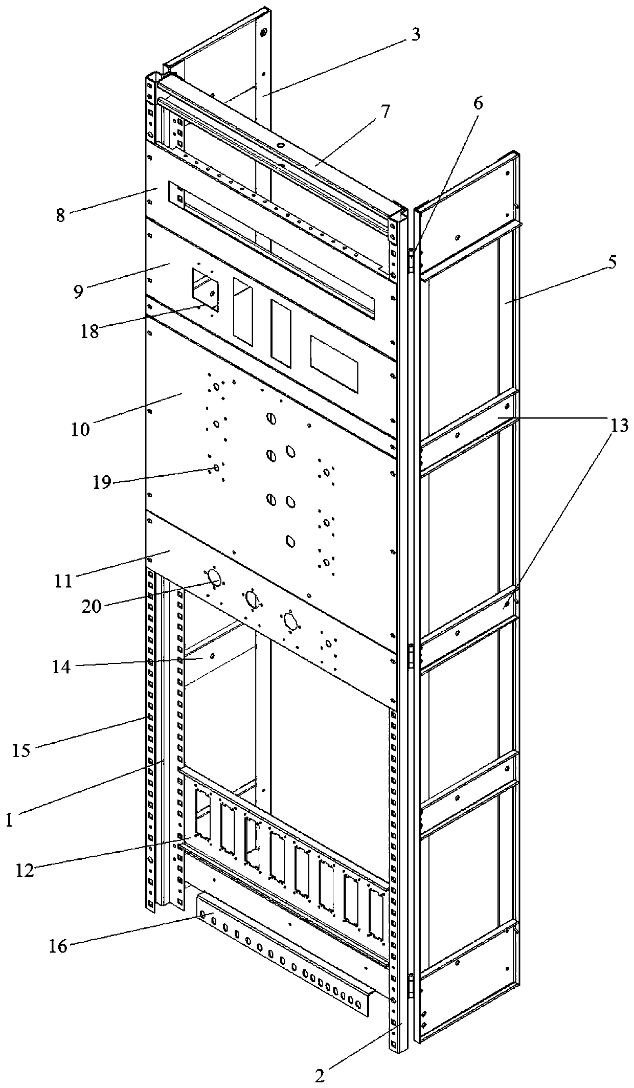
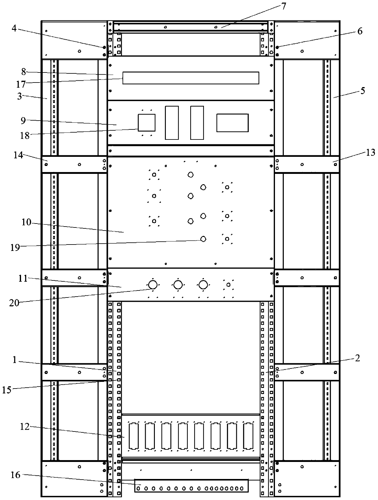
[0019] Such as Figure 1 to Figure 4 As shown, the left side of the left column 1 is connected to the left fixed plate 3 through the first rotating shaft 4, the right side of the right column 2 is connected to the right fixed plate 5 through the second rotating shaft 6, and the upper part of the left column 1 and the right column 2 is passed through a beam 7 connection, the left column 1 and the lower part of the right column 2 are connected through the plug-in board 12, and the left column 1 and the right column 2 are respectively connected to the open panel 8, the indicator mounting plate 9, Simulated line mounting plate 10, transfer switch mounting plate 11; the front faces of the left column 1 and the right column 2 are respectively provided with a number of positioning holes 15, the open panel 8, the indicator mounting plate 9, and the analog line are installed The left...


PUM


Abstract

The present invention relates to the technical field of high, medium and low voltage power transmission and transformation equipment, in particular to a plane installation structure and an installation method of a control cabinet in a GIS combined electrical apparatus. The plane installation structure of the control cabinet in the GIS combined electrical apparatus comprises a left column and a right column and is characterized in that the left side of the left column is connected with a left fixing plate through a first rotating shaft; the right side of the right column is connected with a right fixing plate through a second rotating shaft; the upper parts of the left column and the right column are connected through a crossbeam; the lower parts of the left column and the right column areconnected through a plug-in plate; and an air switch panel, an indicator installation board, an analog line installation board and a change-over switch installation board are sequentially connected between the left column and the right column from top to bottom through snap joint. Compared with the prior art, the assembly is simple; the assembly efficiency is greatly improved; a large number of wires and terminals used for transition among different planes in the prior art are saved; and the wire cost is reduced.

Description

technical field [0001] The invention relates to the technical field of high, medium and low voltage power transmission and transformation equipment, in particular to a planar installation structure and installation method of a control cabinet in a GIS combined electrical appliance. Background technique [0002] At present, the structure of the mainstream control cabinet in China is mainly three-dimensional arrangement, and the components on the panel and the terminals in the cabinet are mostly not on the same plane. Although this design can install various components, the disadvantages are obvious: 1. The excessive distance between components and terminals causes a lot of waste of wires, and the complex structure makes the calculation of wire length inaccurate, which increases a lot of redundancy; 2. Wiring workers need to drill from the back of the cabinet to wire in the cabinet. Limitations not only reduce the efficiency of wiring, but also affect the physical and mental h...

Claims


Application Information

Patent Timeline
Patent Type & Authority Applications(China)
IPC IPC(8): H02B13/00H02B1/04H02B3/00
CPCH02B13/00H02B1/04H02B3/00
Inventor 卞婷婷张馨宇史鑫昱
Owner 上海西电高压开关有限公司
Why Eureka
Try Eureka