
Video monitoring layout optimization method and device based on road network

A technology for video surveillance and layout optimization, applied in CCTV systems, televisions, electrical components, etc., can solve problems such as difficulty in investigation and inability to know, and achieve the effect of improving layout and monitoring without dead ends.

Active Publication Date: 2019-12-20
ZHEJIANG UNIVIEW TECH CO LTD
View PDF9 Cites 9 Cited by
  • Summary
  • Abstract
  • Description
  • Claims
  • Application Information

AI Technical Summary

Problems solved by technology

With so many cameras deployed in the city, it is difficult to check whether the video surveillance network can monitor without dead ends
For a small area, it can be judged by manpower whether the monitoring has been fully covered, but as far as a safe city is concerned, no matter the complexity of the city or the number of cameras has far exceeded the scope that can be checked by manpower. The problem brought about by this is that even if the entire city is highly monitored, it is impossible to know whether there are really no dead ends under surveillance
[0004] Therefore, the optimization of the camera layout of the video surveillance system in the city has always been one of the issues that the industry is more concerned about. In addition to artificially checking and eliminating dead spots in monitoring, there is no better technical solution to solve it.

Method used


Image

  • Video monitoring layout optimization method and device based on road network
  • Video monitoring layout optimization method and device based on road network
  • Video monitoring layout optimization method and device based on road network

Examples


Embodiment Construction

[0032] The technical solution of the present invention will be described in further detail below in conjunction with the accompanying drawings and embodiments, and the following embodiments do not constitute a limitation of the present invention.

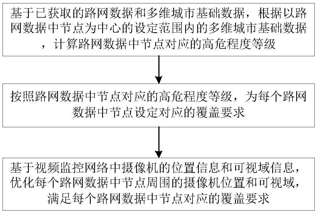
[0033] Such as figure 1 As shown, an embodiment of a road network-based video surveillance layout optimization method is proposed. In this embodiment, a road network-based video surveillance layout optimization method includes:

[0034] Step S1. Based on the obtained road network data and multi-dimensional urban basic data, calculate the high-risk level corresponding to the nodes in the road network data according to the multi-dimensional urban basic data within a set range centered on the nodes in the road network data.

[0035] With the improvement of urban intelligence, the acquisition of urban basic data becomes possible. At present, urban basic data, including but not limited to case data of the public security system, illegal...


PUM


Abstract

The invention discloses a video monitoring layout optimization method and device based on a road network. The method comprises steps of based on acquired road network data and multi-dimensional city basic data, calculating high risk degree levels corresponding to nodes in the road network data; according to the high risk degree levels corresponding to the nodes in the road network data, setting acorresponding coverage requirement for the node in each piece of road network data, and finally optimizing the position and the visual range of the camera around the node in each piece of road networkdata based on the position information and the visual range information of the camera in the video monitoring network, thereby meeting the coverage requirement corresponding to the node in each pieceof road network data. According to the invention, the rationality of urban video monitoring layout is evaluated, the layout of cameras in an urban video monitoring system is improved, and no monitoring dead angle is realized.

Description

technical field [0001] The invention belongs to the technical field of video surveillance layout optimization, and in particular relates to a road network-based video surveillance layout optimization method and device. Background technique [0002] At present, the map-based video monitoring network has been widely used in the daily public security prevention and control and command and dispatch of public security. Through the video application of the map, the video monitoring of the designated location on the map can be carried out in real time. Compared with the traditional monitoring platform, based on the electronic The map monitoring platform can provide better user experience, more real-time point monitoring, more intuitive presentation, and smarter police force dispatching, which will lead to better police prevention and control and case detection. [0003] As the video surveillance network covers more and more areas, the problem of insufficient urban surveillance cove...

Claims


Application Information

Patent Timeline
Patent Type & Authority Applications(China)
IPC IPC(8): H04N7/18
CPCH04N7/181
Inventor 徐炜
Owner ZHEJIANG UNIVIEW TECH CO LTD
Learn More