Heat exchanger and refrigeration cycle device

A heat exchanger and heat transfer tube technology, applied in the field of refrigeration cycle devices, can solve the problems of reduced comfort and reduced average heating capacity, and achieve the effects of improving drainage and heat transfer performance.

Pending Publication Date: 2019-12-20
MITSUBISHI ELECTRIC CORP
View PDF8 Cites 1 Cited by
  • Summary
  • Abstract
  • Description
  • Claims
  • Application Information

AI Technical Summary

Problems solved by technology

As a result, in the case of using a flat tube heat exchanger as an outdoor heat exchanger, it leads to a decrease in comfort and a decrease in average heating capacity

Method used


Image

  • Heat exchanger and refrigeration cycle device
  • Heat exchanger and refrigeration cycle device
  • Heat exchanger and refrigeration cycle device

Examples


Embodiment approach 1

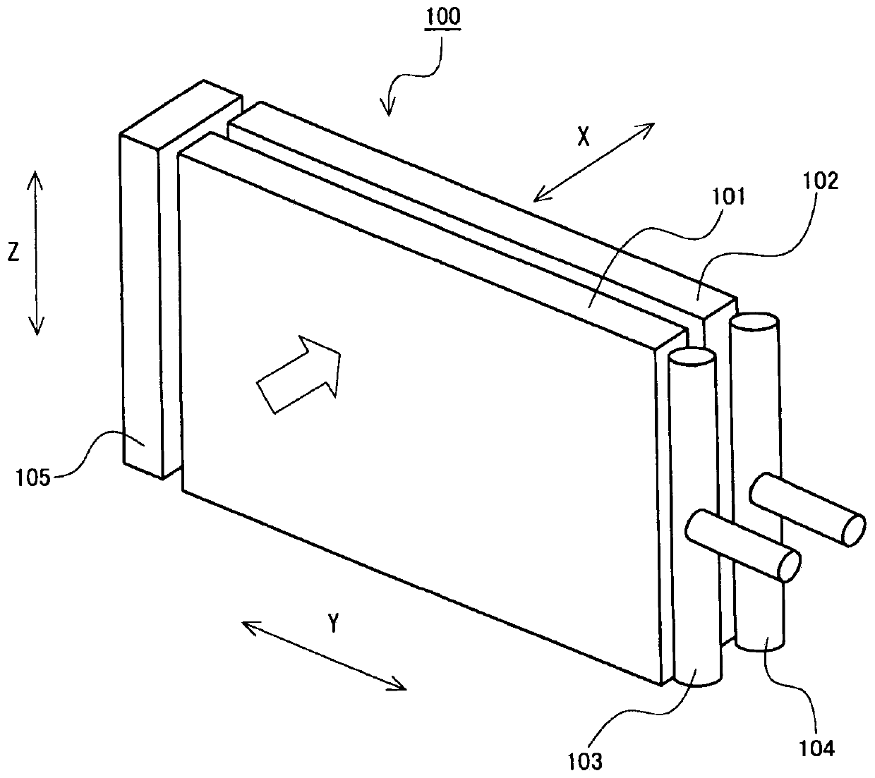
[0035] figure 1 It is a perspective view showing an example of the heat exchanger according to Embodiment 1 of the present invention. also, figure 1 The shown hollow arrows indicate the flow direction of the air supplied from the blower to the heat exchanger 100 .

[0036] As will be described later, the heat exchanger 100 according to Embodiment 1 is a fin-tube heat exchanger having fins 10 and heat transfer tubes 30 . exist figure 1 In the following figures, the horizontal direction and the direction which becomes the short-side direction (width direction) of the fin 10 are called X direction. In addition, the direction which is a horizontal direction and becomes the arrangement direction of the fins 10 which comprise the same heat exchange part (windward side heat exchanger 101 or leeward side heat exchanger 102 mentioned later) is called Y direction. In addition, the vertical direction (gravity direction) and the direction which becomes the longitudinal direction of th...

Embodiment approach 2

[0085] In Embodiment 1, the first inclination angle 21a of the first groove 21 and the second inclination angle 22a of the second groove 22 are set to be substantially the same angle. Not limited thereto, the first inclination angle 21 a of the first groove 21 and the second inclination angle 22 a of the second groove 22 may be different. In addition, in Embodiment 2, items that are not particularly described are the same as in Embodiment 1, and the same functions and configurations are described using the same reference numerals.

[0086] Figure 9 It is a vertical cross-sectional view showing a main part of a heat exchanger according to Embodiment 2 of the present invention. Should Figure 9 from with figure 2 The main part of the heat exchanger 100 of this Embodiment 2 is shown in the same viewing direction.

[0087] as in Figure 9 In the heat exchanger 100 of Embodiment 2, air is supplied from the first end portion 10 a side of the fin 10 by a blower, as indicated b...

Embodiment approach 3

[0092] In Embodiment 1 and Embodiment 2, the heat transfer tube 30 is provided so that the major axis of the cross section is along the horizontal direction (X direction). However, the installation posture of the heat transfer tube 30 is not limited to the installation posture shown in the first embodiment and the second embodiment. For example, the installation posture of the heat transfer tubes 30 of the heat exchanger 100 shown in the first and second embodiments may be set as in the third embodiment. In addition, in Embodiment 3, items that are not particularly described are the same as those in Embodiment 1 or Embodiment 2, and the same functions and configurations are described using the same reference numerals.

[0093] Figure 10 It is a vertical cross-sectional view showing a main part of a heat exchanger according to Embodiment 3 of the present invention. Should Figure 10 from with figure 2 The same viewing direction shows the main part of the heat exchanger 10...


PUM


Abstract

A heat exchanger relating to the present invention is provided with: a fin, which has a first through hole and a second through hole formed therein, and a first end portion and a second end portion; afirst heat transfer tube inserted into the first through hole; and a second heat transfer tube inserted into the second through hole. When a virtual straight line passing end portions of the first heat transfer tube and the second heat transfer tube, said end portions being on the first end portion side, is defined as a first virtual straight line, a virtual straight line passing end portions ofthe first heat transfer tube and the second heat transfer tube, said end portions being on the second end portion side, is defined as a second virtual straight line, a region between the first end portion and the first virtual straight line is defined as a first drain region, a region between the second end portion and the second virtual straight line is defined as a second drain region, and a region surrounded by the first heat transfer tube, the second heat transfer tube, the first virtual straight line, and the second virtual straight line is defined as a water conducting region, a first trench inclined downward toward the first drain region, and a second trench tilted downward toward the second drain region are formed in the water conducting region.

Description

technical field [0001] The present invention relates to a fin-tube heat exchanger and a refrigeration cycle device including the heat exchanger. Background technique [0002] Conventionally, a fin-tube heat exchanger is known that includes a plurality of plate-shaped fins arranged at intervals of predetermined fin pitches, and upper and lower fins at intervals of predetermined intervals. A plurality of heat transfer tubes arranged side by side in the direction and passing through each fin along the direction of the side by side arrangement of the fins. In addition, among such finned tube heat exchangers, heat exchangers using flat tubes as heat transfer tubes have also been proposed. The flat tube is a heat transfer tube whose lateral width is larger than the vertical width in a cross section perpendicular to the flow direction of the refrigerant, for example, a cross section that is oblong or the like. Hereinafter, a finned tube heat exchanger using flat tubes may be refe...

Claims


Application Information

Patent Timeline
Patent Type & Authority Applications(China)
IPC IPC(8): F28F1/32F25B39/02F28F17/00
CPCF25B13/00F25B39/02F28D1/05391F28F1/022F28F1/325F25D17/067
Inventor 前田刚志中村伸八柳晓
Owner MITSUBISHI ELECTRIC CORP
Why Eureka
Try Eureka