[0022] The technical solutions in the embodiments of the present invention will be clearly and completely described below in conjunction with the accompanying drawings in the embodiments of the present invention. Obviously, the described embodiments are only a part of the embodiments of the present invention, rather than all the embodiments. Based on the embodiments of the present invention, all other embodiments obtained by those of ordinary skill in the art without creative work shall fall within the protection scope of the present invention.
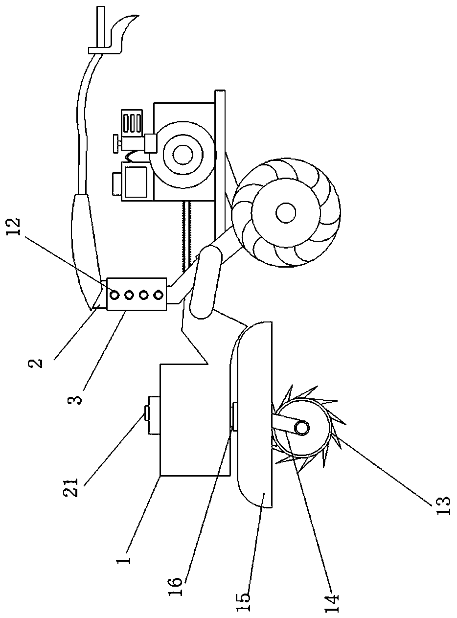
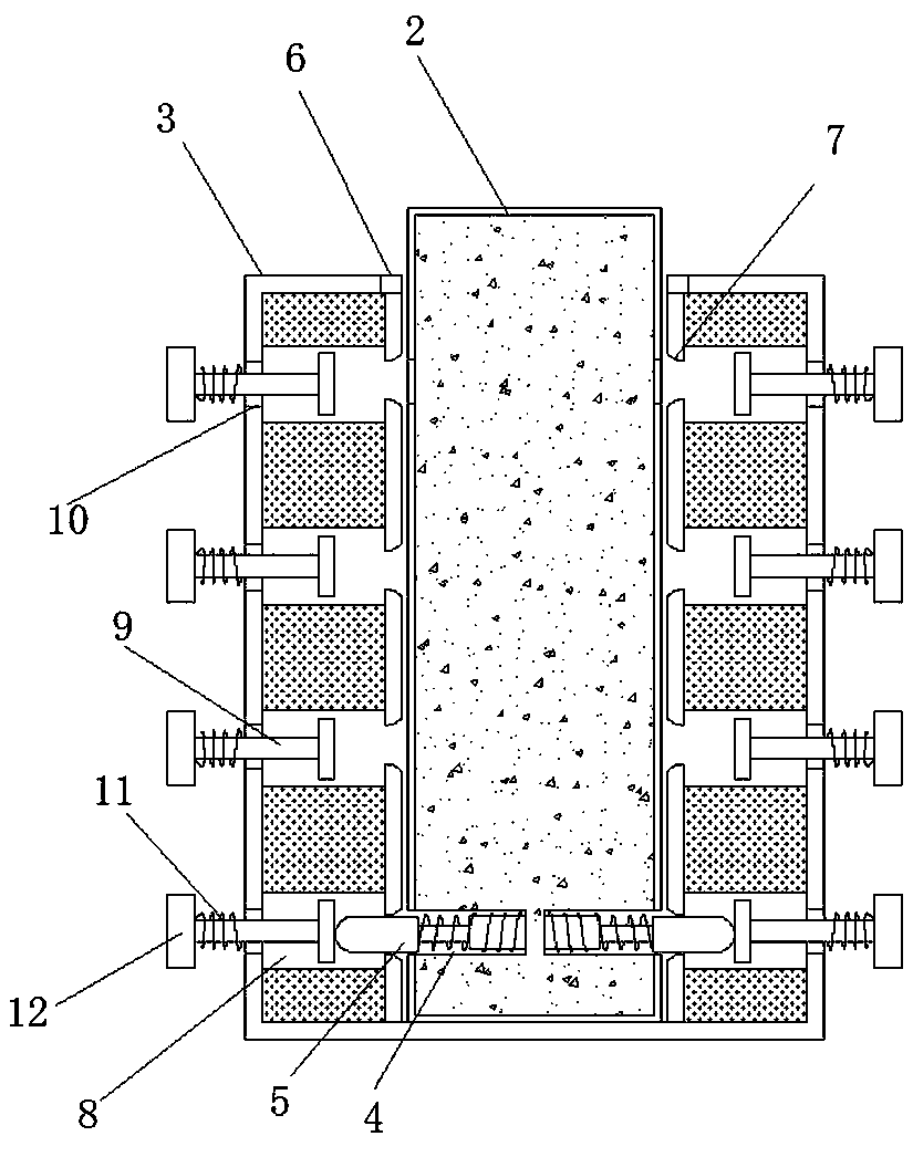
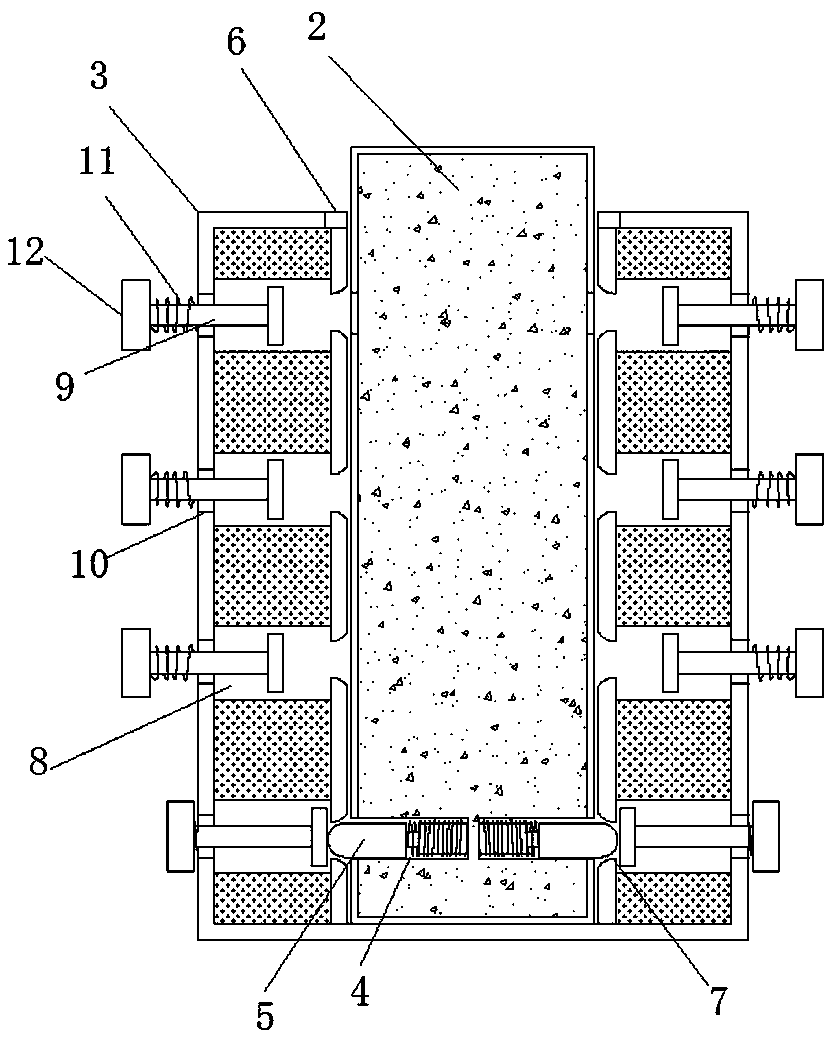
[0023] See Figure 1-6 , An embodiment provided by the present invention: a comprehensive orchard ditching equipment with adjustable spacing, comprising a ditching equipment main body 1, a motor 20 and a motor switch 21. A movable rod 2 is fixed on the ditching equipment main body 1 and is movable The rod 2 passes through the first opening 6 to engage with the engaging sleeve rod 3. The first opening 6 is opened at the upper end of the engaging sleeve rod 3. The front and rear ends of the movable rod 2 are provided with inner grooves 4, and the inner grooves 4 are both A clamping device 5 is fixed. The clamping device 5 includes a clamping block 51, a telescopic rod 52, a telescopic sleeve rod 53, a limit block 54 and a second spring 55. The telescopic sleeve rod 53 is fixed on the inner wall of the inner groove 4, and the telescopic sleeve The rod 53 is connected with a telescopic rod 52, a limit block 54 is fixed on the telescopic rod 52, the outer end of the telescopic rod 52 is fixed with the engaging block 51, and the second spring 55 is wound on the telescopic rod 52 and the telescopic sleeve rod 53. The outer end of the second spring 55 is fixed to the engaging block 51, and the inner end of the second spring 55 is fixed to the inner wall of the inner groove 4. This arrangement allows the engaging block 51 to move in the engaging sleeve rod 3 and the second opening 7. When flush, the engaging block 51 will be bounced into the movable compartment 8 by the restoring force generated by the elasticity of the second spring 55 itself, so that the movable rod 2 is engaged with the engaging sleeve rod 3, and when it is necessary to adjust again, just press Move the two ends to press the plate 12, so that the squeezing rod 9 squeezes the locking block 51 to the second opening 7, and the movable rod 2 can be moved for adjustment. It is simple, quick and easy to operate, so that the staff does not need to bend over and bow. Work with the legs, the outer ends of the engaging device 5 pass through the second opening 7 to fit one end of the extrusion rod 9. The length of the telescopic rod 52 is equal to the pressing length of the extrusion rod 9, ensuring that the engaging block 51 can be squeezed The pressing rod 9 is squeezed to the second opening 7 to move in the movable rod 2. The second openings 7 are all opened on the movable bin 8, and the movable bins 8 are all opened in the engaging sleeve rod 3. The second opening 7 There are four groups, and the shape of the second opening 7 in each group is a slope of "eight". The shape of the second opening 7 is to match the arc shape of the end of the engaging block 51, so that when the worker pulls the movable rod 2, The locking block 51 can be easily separated from the second opening 7 so as to move and adjust along the inner wall of the locking sleeve rod 3. The other end of the extrusion rod 9 passes through the third opening 10 and is fixed to the pressing plate 12. The third openings 10 are all opened on the outer surface of the clamping sleeve rod 3. The surface of the extrusion rod 9 is wound with the first spring 11, and the inner end of the first spring 11 is fixed on the surface of the clamping sleeve rod 3. The outer end of the spring 11 is fixed to the inner end of the pressing plate 12.
[0024] The plowshare 13 is fixed at the bottom end of the main body 1 of the ditching device, and the plowshares 13 are all fixed to the support plate 15 through the connecting rod 14. The upper end of the support plate 15 is symmetrically fixed with a threaded rod 16 and the threaded rod 16 is connected to a threaded sleeve rod. 17 is connected, the threaded sleeve rod 17 is fixed with a pulley 18, the two pulleys 18 are connected by a belt 19, the input end of the rear threaded sleeve rod 17 is connected to the motor 20, and the input end of the motor 20 is connected to the motor switch 21 through a wire The output terminal is electrically connected, the model of the motor 20 is Y90S-2, and the motor 20 is fixed in the main body 1 of the trenching equipment.
[0025] Working principle: When the user needs to adjust the height of the armrest for ditching work, press the pressing plate 12 at the front and rear ends of the engaging sleeve rod 3, and the pressing plate 12 drives the first spring 11 and the pressing rod 9 to squeeze inward. At this time, the inner end of the squeezing rod 9 is squeezed against the engaging blocks 51 at both ends, and the engaging block 51 drives the second spring 55 and the telescopic rod 52 to squeeze and move into the limiting block 54 until the engaging block 51 and the second When the opening 7 is flush, the staff pulls the movable rod 2 so that the engaging block 51 rises along the inner wall of the engaging sleeve rod 3 through the second opening 7 to the next second opening 7. The staff can adjust according to the actual situation. The four heights are adjusted. At this time, the engaging block 51 generates a restoring force due to the elasticity of the second spring 55 itself, and both ends of the engaging block 51 bounce into the movable bin 8 to be engaged and fixed with the engaging sleeve rod 3.
[0026] When the user needs to adjust the depth of the trench, the worker can press the motor switch 21 to start the motor 20. The output end of the motor 20 drives the rear threaded sleeve rod 17 to rotate, and the rear threaded sleeve rod 17 drives the pulley 18 fixed to it to rotate , The pulley 18 drives the other pulley 18 to rotate through the belt 19, the other pulley 18 drives the other threaded rod 17 to rotate at the same time, the two threaded rods 17 both drive the threaded rod 16 to rotate, and the threaded rod 16 starts to rise or fall to drive the support The board 15 rises or falls, and the support board 15 drives the plowshare 13 to rise or fall through the connecting rod 14. From the adjustment of the distance between the plowshare 13 and the ground, the depth of the ditch can be adjusted, and the final operation is over.
[0027] For those skilled in the art, it is obvious that the present invention is not limited to the details of the foregoing exemplary embodiments, and the present invention can be implemented in other specific forms without departing from the spirit or basic characteristics of the present invention. Therefore, from any point of view, the embodiments should be regarded as exemplary and non-limiting. The scope of the present invention is defined by the appended claims rather than the above description, and therefore it is intended to fall within the claims. All changes within the meaning and scope of equivalent elements of are included in the present invention. Any reference signs in the claims should not be regarded as limiting the claims involved.