
A method for processing nozzle ring blades

A processing method and nozzle ring technology, which are applied in the processing field of nozzle ring blades, can solve problems such as dimension measurement, and achieve the effect of ensuring the contour.

Active Publication Date: 2020-10-09
CHONGQING JIANGJIN SHIPBUILDING IND
View PDF13 Cites 0 Cited by
  • Summary
  • Abstract
  • Description
  • Claims
  • Application Information

AI Technical Summary

Problems solved by technology

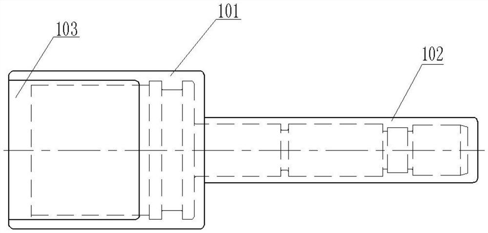
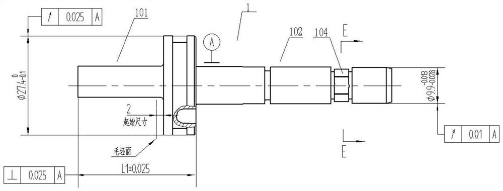
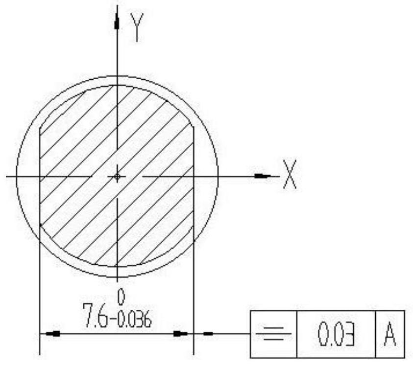
[0004] The purpose of the present invention is to overcome the deficiencies of the prior art and provide a method for processing nozzle ring blades. Through the design of special fixtures, the milling of nozzle ring blades and the processing of flat shaft ends are realized, and at the same time, auxiliary measuring tools are designed to solve part of the size measurement. The problem

Method used


Image

  • A method for processing nozzle ring blades
  • A method for processing nozzle ring blades
  • A method for processing nozzle ring blades

Examples


Embodiment Construction

[0054] Such as Figure 1 to Figure 16 Shown, a kind of processing method of nozzle ring vane, comprises the following steps:

[0055] Step 1 rough car

[0056] The outer circle of the three-jaw clamp shaft end 102, after alignment, remove the outer circle margin of the blade end 101;

[0057] The specific processing method, according to the attached Figure 5 Rough car;

[0058] Step 2 semi-finished car

[0059] The outer circle of the blade end 101 of the three-claw clamp, after alignment, the runout of the outer circle of the car is not greater than 0.02, according to the attached Figure 6 Remove the outer circle and end face allowance of the shaft end 102;

[0060] Step 3 rough milling blade, fine milling blade shape

[0061]Use the milling tool to position and clamp the blades of the nozzle ring, take the outer circle of the shaft end and the large end surface in step 2 as the positioning surface, and flatten the large end surface, first rough mill the blade, and th...


PUM


Abstract

The invention discloses a machining method for a nozzle ring blade. The machining method comprises the following steps that the outer circle allowance of the blade end is removed; the shaft end outercircle and end face allowances are removed, and subsequent machining locating faces are obtained; the nozzle ring blade is located and clamped by a milling tool, the shaft end outer circle and the large end face serve as locating faces, the large end face is flattened, the blade is milled roughly first, then finish milling is conducted for the blade profile, and the profile tolerance of the bladeprofile is ensured; finish turning is conducted on the shaft end face, the outer circle and a shaft end face chamfer; the shaft end face is flattened, and finish turning is conducted on the blade endouter circle and an annular groove; the nozzle ring blade is clamped by a turning tool, the blade profile serves as a locating face, the top end of the blade is flattened, and a shaft end flat squareis formed by cutting; and a bench worker removes burrs. The special milling tool and the turning tool are designed, thus the nozzle ring blade is milled, the shaft end flat square is machined, and meanwhile, an auxiliary measuring tool is designed to solve the problem of partial dimension measurement.

Description

technical field [0001] The invention relates to the field of engine machining of ships and warships, in particular to a method for machining nozzle ring blades. Background technique [0002] The marine mixed-flow turbocharger, as a supporting part of the diesel engine, is a pressure ratio adjustable supercharger product independently developed by the company. The nozzle ring is an important component of this type of product. The size of the air intake is adjusted to design the indexable nozzle ring blades, which have strict requirements for matching with the surrounding components. The material of the parts is made of cast stainless steel (G-X05CrNiMo19-11-2), and the two-position positioning gear at the shaft end has a dimensional tolerance And the shape and position tolerance requirements are high, and there is a relative positional relationship between the blade and the flat square of the shaft end. In the process of processing, these demanding dimensional tolerances and...

Claims


Application Information

Patent Timeline
Patent Type & Authority Patents(China)
IPC IPC(8): B23P15/02
CPCB23P15/02
Inventor 杨川华李成科段昌文袁列军
Owner CHONGQING JIANGJIN SHIPBUILDING IND
Learn More