Light corrugated pipe type thermal expansion driving device

A drive device, bellows-type technology, applied in valve devices, valve operation/release devices, engine components, etc., can solve problems such as increasing product complexity, large displacement drive requirements, and difficulties, and achieves a clear working principle. , the effect of novel device structure

Pending Publication Date: 2019-12-24
YANGZHOU UNIV
View PDF0 Cites 1 Cited by
  • Summary
  • Abstract
  • Description
  • Claims
  • Application Information

AI Technical Summary

Problems solved by technology

The current thermal expansion driver, that is, the body of the above-mentioned temperature sensing package is composed of a copper container, and the container is filled with an expansion medium such as paraffin. When the expansion medium expands to fill the container, the outward driving displacement will stop, because the driver body does not No scalability, the disadvantage of the lack of scalability of the body restricts its development of large displacement drives
In addition, because the main body cannot be stretched and contracted, the thermal expansion driver is under huge pressure in the latter part of the expansion period. In order to ensure the safety and reliability of the driver, the driver body is often made of thicker metal, resulting in a larger weight. The sealing process is more stringent and difficult
Nowadays, especially in some industrial fields, there is a great demand for large displacement drives. The original method is to install mechanical structures such as displacement amplifiers inside the temperature control valve, which not only increases the production cost, but also increases the complexity of the product. Its work The reliability is greatly reduced, so it is necessary to design a thermal expansion drive device to meet the needs of use

Method used


Image

  • Light corrugated pipe type thermal expansion driving device
  • Light corrugated pipe type thermal expansion driving device
  • Light corrugated pipe type thermal expansion driving device

Examples


Embodiment Construction

[0015] The present invention will be further described below in conjunction with accompanying drawing:

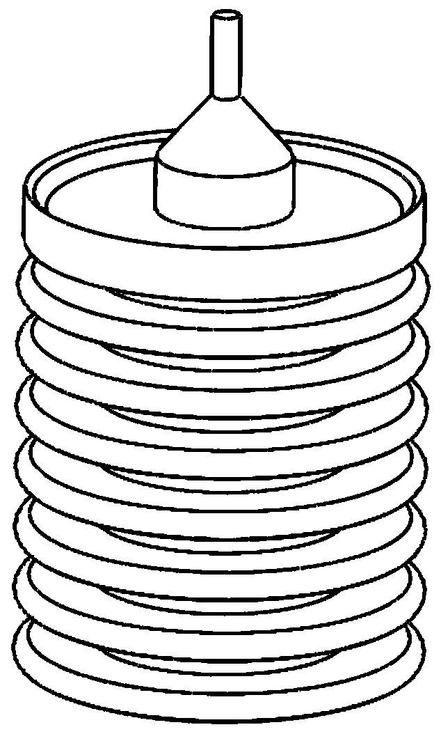
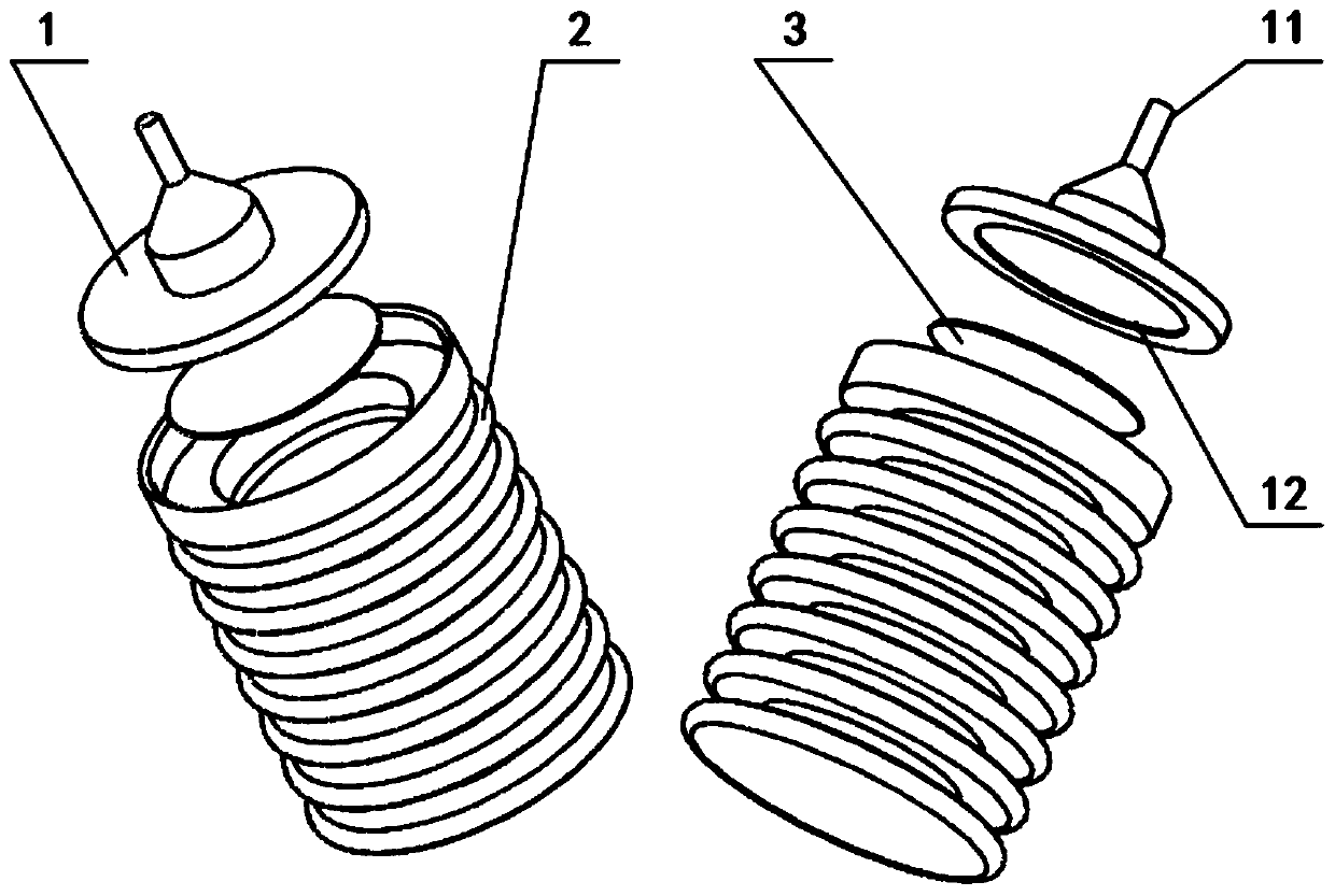
[0016] Such as Figure 1-4 As shown, a light-weight bellows type thermal expansion drive device is composed of a bellows body 2, a top cover 1, a sealing gasket 3 and a thermal expansion medium 4; the outer surface of the bellows body 2 is uniformly provided with several U-shaped grooves , the inside of the bellows body 2 is a hollow structure, and the thermal expansion medium 4 is filled in the hollow structure, the bottom of the bellows body 2 is a sealed structure, the top of the bellows body 2 is provided with an opening, and the top cover 1 is arranged outside the opening. The front of the cover 1 is provided with a push rod 11, the back of the top cover 1 is provided with a groove 12, and the groove 12 is provided with a gasket 3, and the top cover 1 forms a sealed connection with the top of the bellows body 2 through the gasket 3.

[0017] Such as Figure 1-4 As sh...


PUM


Abstract

The invention discloses a light corrugated pipe type thermal expansion driving device, and belongs to the field of thermal expansion braking. The driving device is composed of a corrugated pipe body,a top cover, a sealing gasket and a thermal expansion medium. The device has the advantages of being novel structure and clear in working principle; a corrugated pipe body in the device can be used asa temperature sensing body filled with the thermal expansion medium, but also as an elastic element to directly sense the volume change of the thermal expansion medium so that displacement output canbe directly converted; and meanwhile contracting and stretching of the corrugated pipe can be realized by means of thermal expansion and contraction properties of the thermal expansion medium so as to drive a push rod in a temperature control valve to realize the backward and forward displacement, so that the conversion of thermal energy and mechanical energy is realized, and the output of the maximum displacement can be realized as well.

Description

technical field [0001] The invention belongs to the field of thermal expansion braking, and relates to a thermal expansion drive device, in particular to a light bellows type thermal expansion drive device which utilizes thermal expansion and contraction to realize conversion between thermal energy and mechanical energy. Background technique [0002] At present, thermal expansion braking is used in many fields, such as temperature control valves, which are widely used in the control of working fluid temperature and flow in various thermal equipment. As the core component of the thermostatic valve, the thermal expansion driver determines the performance of the thermostatic valve. A self-operated thermal expansion driver widely used at present is a paraffin temperature-sensing package, which is composed of a temperature-sensing package body, paraffin, a push rod, and rubber. The temperature sensing package has excellent performance in the field of micro-drive (less than 5mm),...

Claims


Application Information

Patent Timeline
Patent Type & Authority Applications(China)
IPC IPC(8): F03G7/06F16K31/70
CPCF03G7/06F16K31/002
Inventor 王霁翔王红梅徐祥毛羽丰熊凯
Owner YANGZHOU UNIV
Why Eureka
Try Eureka