Novel air valve structure

A damper, a new type of technology, applied in the direction of the valve shell structure, sliding valve, valve details, etc., can solve the problem of reduced air intake and exhaust air volume, and achieve the effect of large ventilation air volume, small area and good effect

Pending Publication Date: 2019-12-24
HAOTING (TANGSHAN) ENVIRONMENTAL TECH CO LTD
View PDF0 Cites 3 Cited by
  • Summary
  • Abstract
  • Description
  • Claims
  • Application Information

AI Technical Summary

Problems solved by technology

Due to the limited indoor space and in order not to affect the interior decoration effect, the volume of the damper needs to be as small as possible, but the reduction of the volume of the damper will reduce the air volume of the air intake and exhaust

Method used


Image

  • Novel air valve structure
  • Novel air valve structure
  • Novel air valve structure

Examples


Embodiment Construction

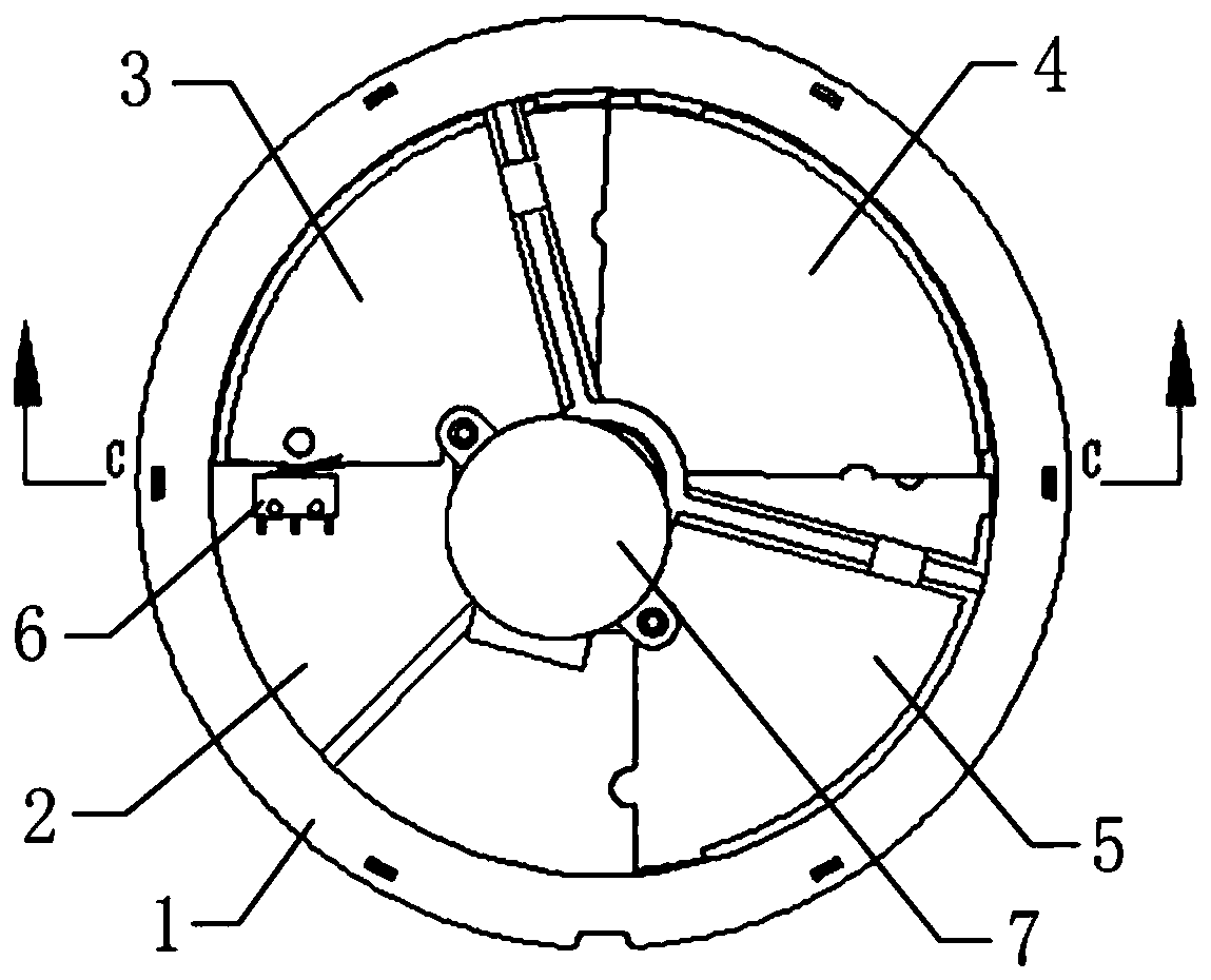
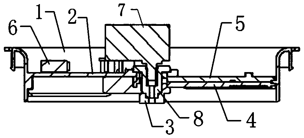
[0025] The technical solution of the present invention will be described in detail, clearly and completely below in conjunction with the accompanying drawings. What needs to be explained in advance is that the words "up" and "down" used to indicate the direction in this description are appended figure 1 , 2 The upper and lower positions of the fan-shaped blades are determined; the words "left" and "right" are used to describe the orientation of the fan-shaped blades in this note. Clockwise side. The "forward rotation" and "reverse rotation" mentioned in the present invention are only for the convenience of distinguishing the rotation direction of the fan blades, and it does not mean that the corresponding results must be obtained through forward rotation or reverse rotation. The terms used to indicate orientation in the present invention are only defined for the convenience of description, and do not mean that the corresponding components must have corresponding positions or...


PUM


Abstract

The invention provides a novel air valve structure. The novel air valve structure is characterized in that a plurality of fan-shaped blades are arranged in a air valve frame, the novel air valve structure further comprises a microswitch, a stepping motor and a rotating shaft, the fan-shaped blades comprise first fans, tail fans and a plurality of middle fans, shaft sleeves of the tail fans are fixedly connected with the bottom end of the rotating shaft, the middle fans and shaft sleeves of the first fans are sequentially sleeved on the rotating shaft, the upper surfaces of the left sides of the tail fans are provided with leaf collecting columns which extend upwards to the height in which the first fans are located, linkage shifting blocks are arranged on the upper surface of the right side of the tail fans, linkage shifting plates are arranged on the lower surface of the left sides of the middle fans, linkage shifting blocks are arranged on the upper surfaces of the right sides of themiddle fans, the first fans are fixedly connected with the air valve frame, the lower surfaces of the left sides of the first fans are provided with linkage shifting plates, the lower surfaces of theright sides of the first fans are provided with limiting columns which extend downwards to the height in which the tail fans are located, the linkage shifting block of each fan blade is located on the inner side of the upper layer of fan blade linkage the shifting plate, when the tail fans are forward rotated, all the middle fans are folded in sequence by pushing, and when the tail fans are reversal rotated, the middle fans are sequentially pulled out from the the first fans. The novel air valve structure is higher in ventilation air volume but smaller in occupied area.

Description

technical field [0001] The invention belongs to the technical field of air purification equipment, and in particular relates to a novel damper structure. Background technique [0002] As people pay more attention to indoor air quality, more and more fresh air fans and their supporting equipment have entered ordinary families. Different from air purifiers, fresh air fans purify the outdoor air and discharge it into the room, and discharge indoor dirty air to the outside. Therefore, it is necessary to open holes in the walls or windows and install ventilation dampers. Due to the limited indoor space and in order not to affect the interior decoration effect, the volume of the damper needs to be as small as possible, but the reduction of the volume of the damper will reduce the air volume of the air intake and exhaust. The volume of the ventilation damper affects the ventilation air volume. How to increase the ventilation volume on the basis of using a damper with the smallest ...

Claims


Application Information

Patent Timeline
Patent Type & Authority Applications(China)
IPC IPC(8): F16K3/08F16K3/314F16K3/30F16K3/316F16K27/04F16K31/04
CPCF16K3/029F16K3/085F16K3/30F16K3/314F16K3/316F16K27/045F16K31/043
Inventor 刘小林王冠永王盛楠艾程双高玉增
Owner HAOTING (TANGSHAN) ENVIRONMENTAL TECH CO LTD
Why Eureka
Try Eureka