Target pose measurement system and method based on feature point position correction

A technology of pose measurement and feature points, applied in image analysis, image enhancement, instruments, etc., can solve the problems of inapplicability to large-scale monitoring of roadbed settlement, large volume cannot install roadbed settlement monitoring system, high monitoring cost, etc., to reduce The number of manual interventions and the workload of manual inspections, the effect of improving work efficiency and detection accuracy

Active Publication Date: 2019-12-24
LANZHOU JIAOTONG UNIV
View PDF4 Cites 1 Cited by
  • Summary
  • Abstract
  • Description
  • Claims
  • Application Information

AI Technical Summary

Problems solved by technology

In the prior art, a method of converting an unstable measurement platform based on a transfer camera to a static reference is proposed. This method enables dynamic measurement with high precision even on an unstable platform, but it cannot be installed on an unstable platform due to its large size. Subgrade settlement monitoring system
In addition, the inclination sensor is used to provide multiple angle constraints, and a measurement system combining monocular vision and inclination sensor is designed. Although the measurement accuracy and stability of the system are improved, the monitoring cost is high and it is not suitable for large-scale subgrade settlement. monitor

Method used


Image

  • Target pose measurement system and method based on feature point position correction
  • Target pose measurement system and method based on feature point position correction
  • Target pose measurement system and method based on feature point position correction

Examples


Embodiment 1

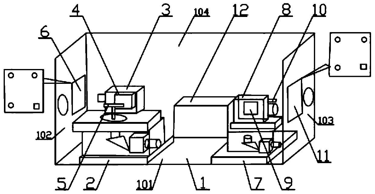
[0034] A target pose measurement system based on feature point position correction, such as figure 1As shown, it includes a seat body 1, which is characterized in that: a first adjustable bracket 2 and a second adjustable bracket 7 are installed on the bottom plate 101 of the seat body 1, and the first adjustable bracket 2 and the second adjustable bracket The brackets 7 are respectively located on the left side and the right side of the base plate 101. The first camera 3 and the first laser 5 are installed on the upper surface of the first adjustable bracket 2, and the first camera 3 is installed on the side of the first camera 3. An inclinometer 4, a second camera 8 and a second laser 10 are installed on the upper surface of the second adjustable bracket 7, a second inclinometer 9 is installed on the side of the second camera 8, and the base 1 The first feature point target surface 6 is provided on the left side plate 102 of the base body 1, the second feature point target s...

Embodiment 2

[0040] While the image-based subgrade settlement monitoring system transmits the settlement deformation information, it also accumulates and transmits the measurement errors of each transmission detection station. The final measurement accuracy will inevitably decrease with the increase in the number of transmission detection stations. The measurement error between the detection stations is transmitted, and the closed adjustment method in the railway subgrade surface settlement observation standard is used for reference, and the chain measurement method is constructed into a closed loop, and the accumulated error is eliminated by the closed adjustment method.

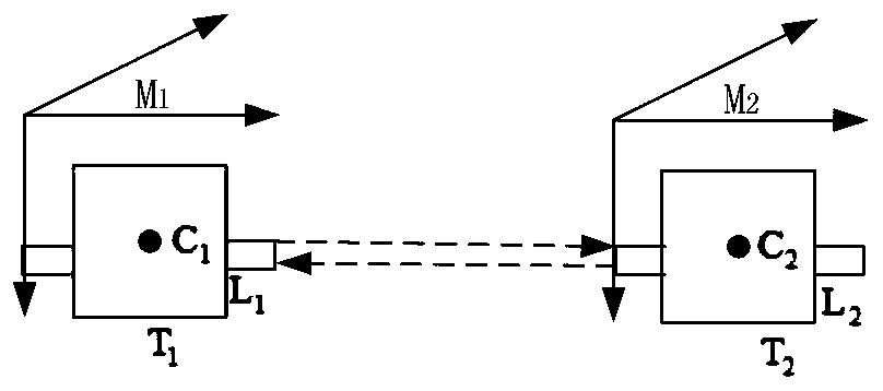
[0041] Such as figure 2 A closed loop is formed between the bit transfer stations shown. Every two adjacent measurement base stations in the round-trip dual camera chain are T 1 and T 2 , L, C, M are the light source, camera and target surface of the monitoring system, respectively. Light source L 1 where the coord...

Embodiment 3

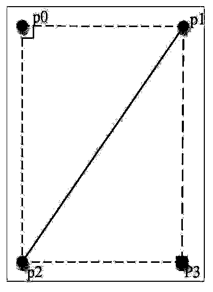
[0045] The correction of feature points is divided into feature point integrity type position correction and feature point missing type position correction. When the target surface or camera deflection angle is small or the background clarity is high, the number of feature points that can be collected is K=4, which can be The accuracy of centroid location of feature points and the integrity of image acquisition are judged by l and d of rectangular feature points. Such as image 3 As shown, the experimentally obtained feature point p 0 ,p 1 ,p 2 ,p 3 After the pixel coordinate value, use any one of the four feature points as an example p 0 Click to verify, Figure 5 It is a flow chart of complete position correction. First according to p 0 p 1 = d, p 0 p 2 = l and p 0 p 1 ⊥p 0 p 2 carry on p 0 with p 2 position, and then calculate p 3 Pixel coordinate value, and finally compare the calculated feature point coordinate value with the feature point positioning val...


PUM


Abstract

The invention relates to the technical field of roadbed settlement measurement, in particular to a target pose measurement system and method based on feature point position correction, and aims to overcome the defects in the prior art and provide the target pose measurement system and method based on feature point position correction. The system comprises a first camera and a first laser. A firstinclinometer is mounted on the side surface of the first camera; a second camera and a second laser are mounted on the upper surface of the second adjustable bracket; a second inclinometer is mountedon the side surface of the second camera; a first feature point target surface is arranged on a left side plate of the base body; a second feature point target surface is arranged on a right side plate of the base body; the method has the advantages that a pose measurement system different from a feature point target surface of a traditional feature point is designed according to actual operationconditions, a pose solving method with known rectangular feature point side length is provided in combination with a specific four-feature-point target surface, and the relative pose between the target surface and a camera can be accurately solved.

Description

technical field [0001] The invention relates to the technical field of subgrade settlement measurement, in particular to a target pose measurement system and method based on feature point position correction. Background technique [0002] As a key part of rail transit engineering, the subgrade is the basic bearing system of the track structure and train load. If there is structural deformation, it will not only cause deformation of the track, but also cause serious train vibration and even safety accidents. Therefore, in order to ensure the safe operation of trains, effective measures should be taken to accurately control the post-construction settlement and deformation of the railway ballastless track. Traditional monitoring methods include observation pile method, settling plate method, settling water cup method, and sensor monitoring method. Although these methods are easy to install, they require manual point-by-point measurement, cannot be automatically monitored, and a...

Claims


Application Information

Patent Timeline
Patent Type & Authority Applications(China)
IPC IPC(8): G06T7/70G06T7/13G06T7/00
CPCG06T7/70G06T7/13G06T7/0002G06T2207/10004G06T2207/20064G06T2207/20192
Inventor 闵永智陶佳党建武张振海张雁鹏林俊亭张鑫左静岳彪
Owner LANZHOU JIAOTONG UNIV
Why Eureka
Try Eureka