
Rapid antenna deployment method and narrowband antenna

An antenna and fast technology, applied to antenna components, antennas, radiating element structures, etc., can solve the problems of inflexible antenna deployment, poor adaptability, and poor concealment, so as to avoid heavy handling, easy to carry, and improve concealment Effect

Active Publication Date: 2019-12-24
BEIJING DREAM INK TECH CO LTD
View PDF7 Cites 0 Cited by
  • Summary
  • Abstract
  • Description
  • Claims
  • Application Information

AI Technical Summary

Problems solved by technology

[0004] In view of this, an object of the present invention is to propose a rapid antenna deployment method to solve the problems of inflexible antenna deployment, poor adaptability, and poor concealment in the prior art

Method used


Image

  • Rapid antenna deployment method and narrowband antenna
  • Rapid antenna deployment method and narrowband antenna
  • Rapid antenna deployment method and narrowband antenna

Examples


Embodiment Construction

[0026] The following description and drawings illustrate specific embodiments of the invention sufficiently to enable those skilled in the art to practice them. Other embodiments may incorporate structural, logical, electrical, process, and other changes. The examples merely represent possible variations. Individual components and functions are optional unless explicitly required, and the order of operations may vary. Portions and features of some embodiments may be included in or substituted for those of other embodiments. The scope of embodiments of the present invention includes the full scope of the claims, and all available equivalents of the claims. These embodiments of the present invention may be referred to herein, individually or collectively, by the term "invention", which is for convenience only and is not intended to automatically limit the application if in fact more than one invention is disclosed The scope is any individual invention or inventive concept.

...


PUM

PropertyMeasurementUnit
melting pointaaaaaaaaaa

Abstract

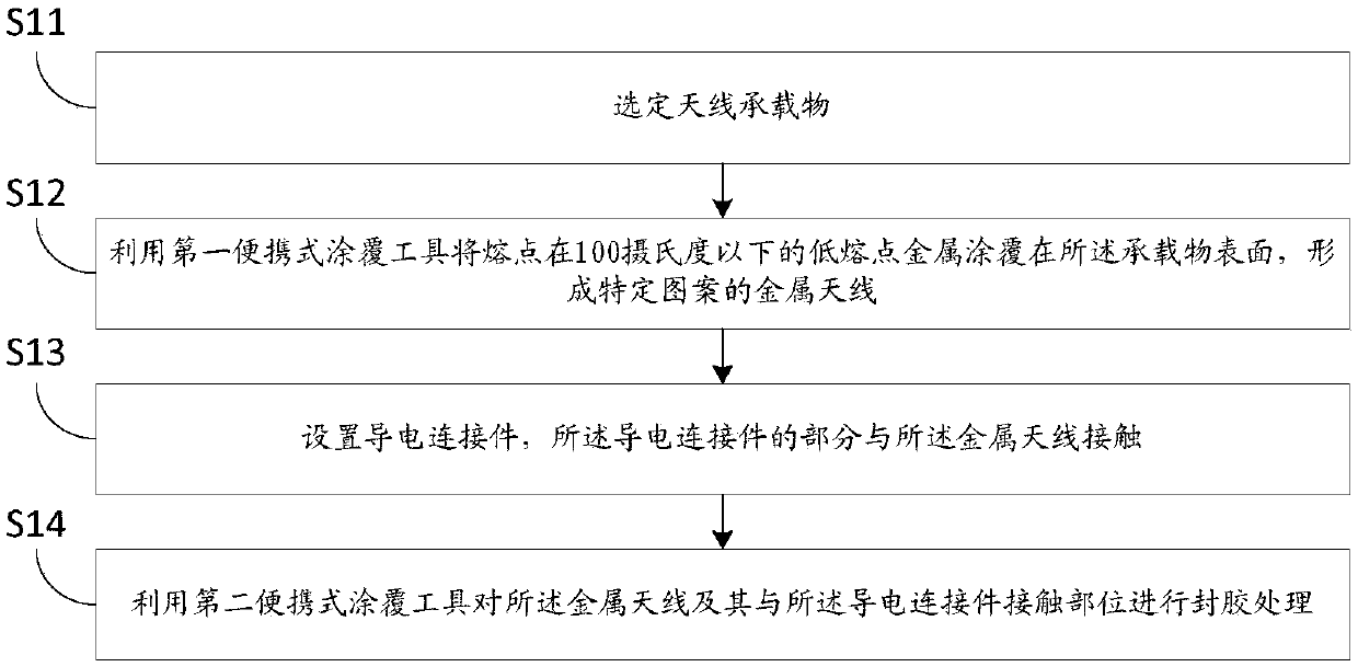
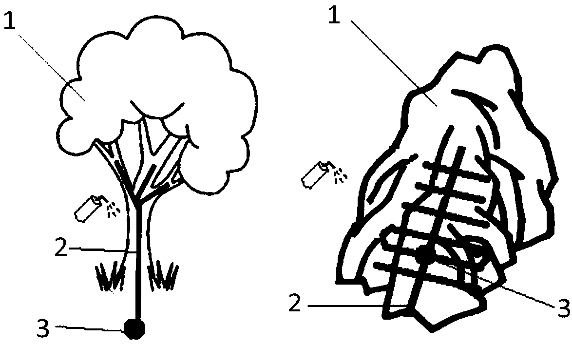
The invention provides a rapid antenna deployment method and a narrowband antenna. The method comprises the steps that an antenna carrier is selected; a first portable coating tool is used to coat thesurface of the carrier with low melting point metal with a melting point below 100 DEG C to form a specific-patterned metal antenna; and a conductive connector is provided, wherein a part of the conductive connector contacts the metal antenna. According to the invention, the method of coating the low melting point metal is used to deploy the antenna in any environment and at any location, which is more convenient for the deployment of an outdoor communication antenna; at the same time the coating can be performed on any carrier such as trees, rocks, walls and the ground; the concealment of the antenna can be improved through the selection of some positions; in addition, the antenna can be custom designed and manufactured according to the actual antenna frequency requirement of a user; theantenna deployment tool provided by the invention is easy to carry, and avoids the problem of heavy handling of traditional antenna deployment.

Description

technical field [0001] The invention belongs to the technical field of radio frequency component preparation, and in particular relates to a rapid antenna deployment method and a narrowband antenna. Background technique [0002] An antenna is a transformer that transforms a guided wave propagating on a transmission line into an electromagnetic wave propagating in an unbounded medium (usually free space), or vice versa. A component used in radio equipment to transmit or receive electromagnetic waves. Engineering systems such as radio communication, broadcasting, television, radar, navigation, electronic countermeasures, remote sensing, and radio astronomy, which use electromagnetic waves to transmit information, rely on antennas to work. In addition, in terms of transmitting energy with electromagnetic waves, non-signal energy radiation also requires antennas. Generally, antennas are reversible, that is, the same antenna can be used as both a transmitting antenna and a rece...

Claims


Application Information

Patent Timeline
Patent Type & Authority Applications(China)
IPC IPC(8): H01Q1/36H01Q1/38H01Q19/30
CPCH01Q1/364H01Q1/38H01Q19/30
Inventor 刘凤鸣
Owner BEIJING DREAM INK TECH CO LTD
Learn More