A method and device for determining a communication dead zone

A technology of blind spots and communication times, applied in the field of communication, can solve problems such as poor user experience, achieve comprehensive data, reduce statistical deviation, and improve user experience

Active Publication Date: 2022-07-15
CHINA UNITED NETWORK COMM GRP CO LTD
View PDF8 Cites 0 Cited by
  • Summary
  • Abstract
  • Description
  • Claims
  • Application Information

AI Technical Summary

Problems solved by technology

[0004] To this end, the present invention provides a method and device for determining communication blind spots, so as to solve the problem of poor user experience in the prior art due to the inability to find communication blind spots in time

Method used


Image

  • A method and device for determining a communication dead zone
  • A method and device for determining a communication dead zone
  • A method and device for determining a communication dead zone

Examples


Embodiment Construction

[0027] The specific embodiments of the present invention will be described in detail below with reference to the accompanying drawings. It should be understood that the specific embodiments described herein are only used to illustrate and explain the present invention, but not to limit the present invention.

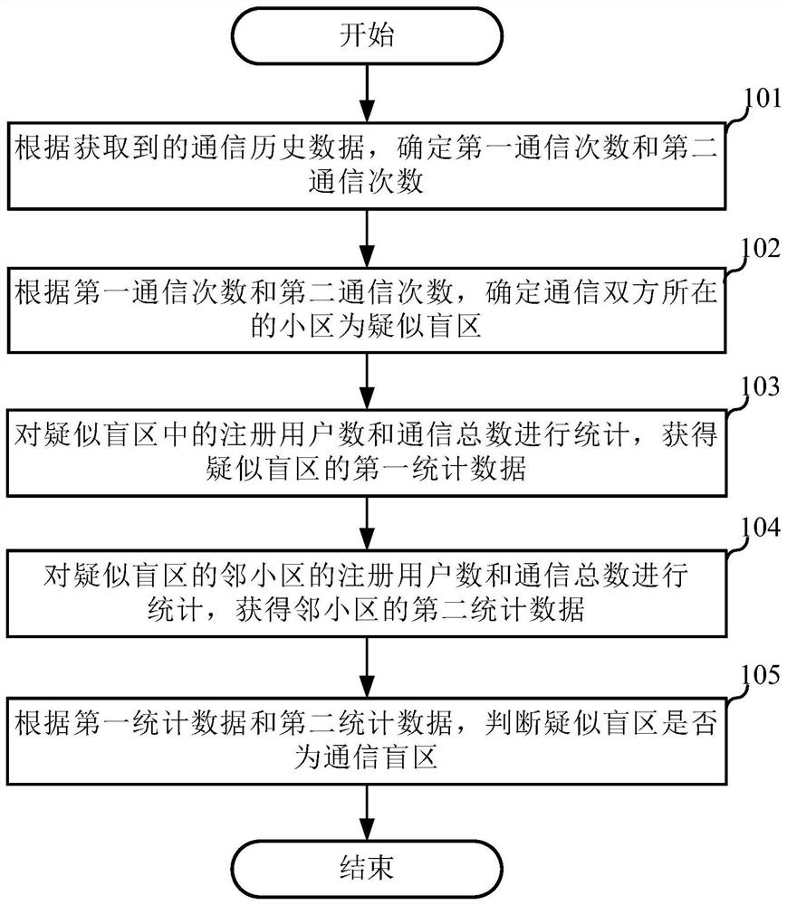
[0028] The first embodiment of the present invention relates to a method of determining a communication dead zone. It is used to discover communication blind spots in time, so that operators can build base stations in the communication blind spots and improve user experience.

[0029] The implementation details of the method for determining a communication dead zone in this embodiment will be specifically described below. The following content is only for the convenience of understanding the implementation details of this solution, and is not necessary for implementing this solution.

[0030] figure 1 This is a flowchart of the method for determining a communication de...


PUM


Abstract

The invention discloses a method and a device for determining a communication blind area. The method includes: determining a first number of communications and a second number of communications according to acquired communication history data, where the first number of communications is the number of consecutively interrupted communications, and the second number of communications is the number of consecutively interrupted communications. The number of communications is the number of communications determined according to the first number of communications and the identification code corresponding to the communication; according to the first number of communications and the second number of communications, it is determined that the cell where the two communicating parties are located is a suspected blind area; the number of registered users in the suspected blind area and the number of communications Count the total number to obtain the first statistical data of the suspected blind area; make statistics on the number of registered users and the total number of communications of the adjacent cells in the suspected blind area, and obtain the second statistical data of the adjacent cells; according to the first statistical data and the second statistical data, determine Whether the suspected blind spot is a communication blind spot. It enables network operators to discover communication blind spots in time, and build base stations in the communication blind spots, thereby improving user experience and bringing greater economic benefits to operators.

Description

technical field [0001] The present invention relates to the field of communication technologies, and in particular, to a method and a device for determining a communication blind area. Background technique [0002] With the development of communication technology, the Internet has become very popular. However, due to limited communication resources, it is impossible for the mobile network to cover all areas, and the areas that cannot be covered by the mobile network can be called communication blind spots. [0003] In the prior art, operators can know which areas have blind spots through complaints from mobile phone users, operators dispatched staff to detect blind spots, or through monitoring software installed on mobile phones to interact with servers. However, none of the above methods can make the operator discover the communication blind spot in time, and the labor cost is high. When the user enters the communication blind spot, the signal strength of the user will dec...

Claims


Application Information

Patent Timeline
Patent Type & Authority Patents(China)
IPC IPC(8): H04W24/02H04W24/08
CPCH04W24/02H04W24/08
Inventor 王子奇
Owner CHINA UNITED NETWORK COMM GRP CO LTD
Why Eureka
Try Eureka