

Head mountable device
A head-mounted device, head technology, used in medical science, telemetry patient monitoring, sensors, etc., can solve the problems of mild traumatic brain injury diagnosis errors, inaccuracy and other problems
- Summary
- Abstract
- Description
- Claims
- Application Information
AI Technical Summary
Problems solved by technology
Method used
Image

Examples
example 1
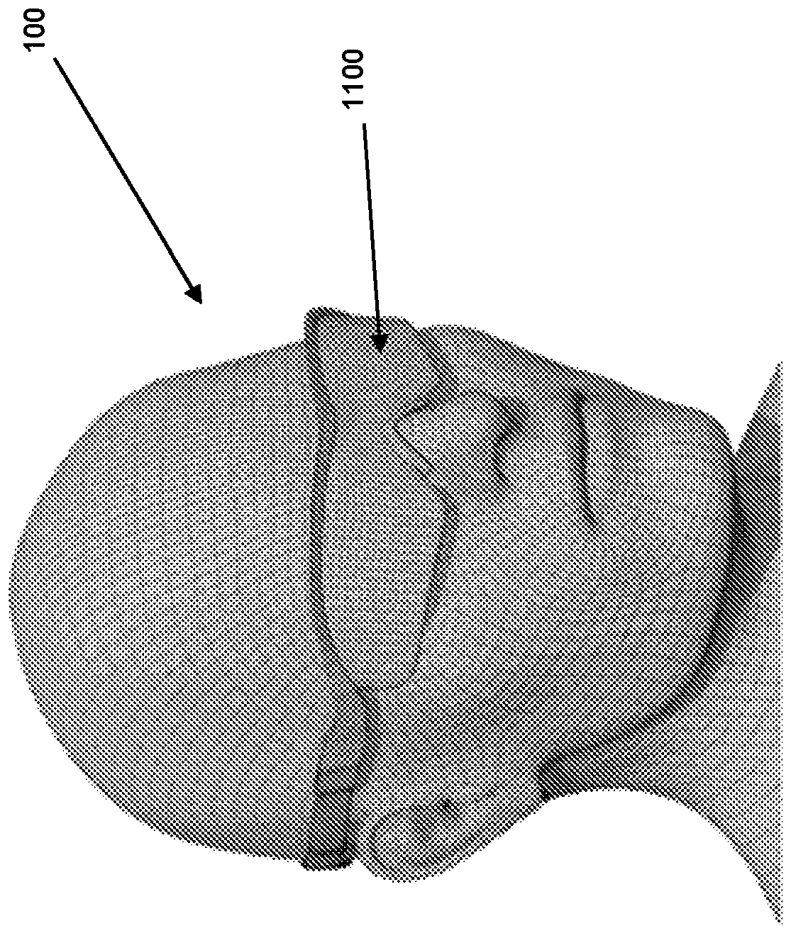
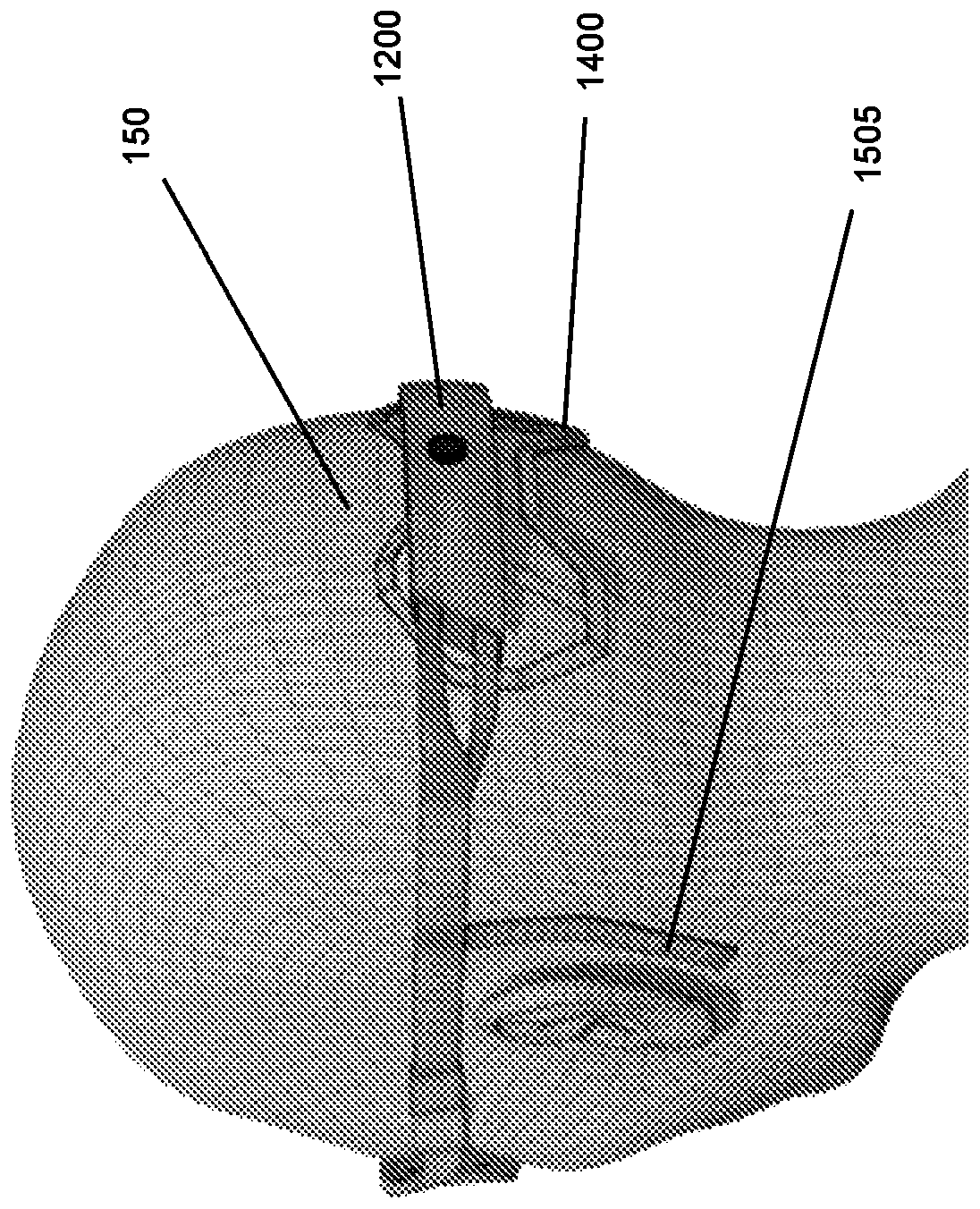
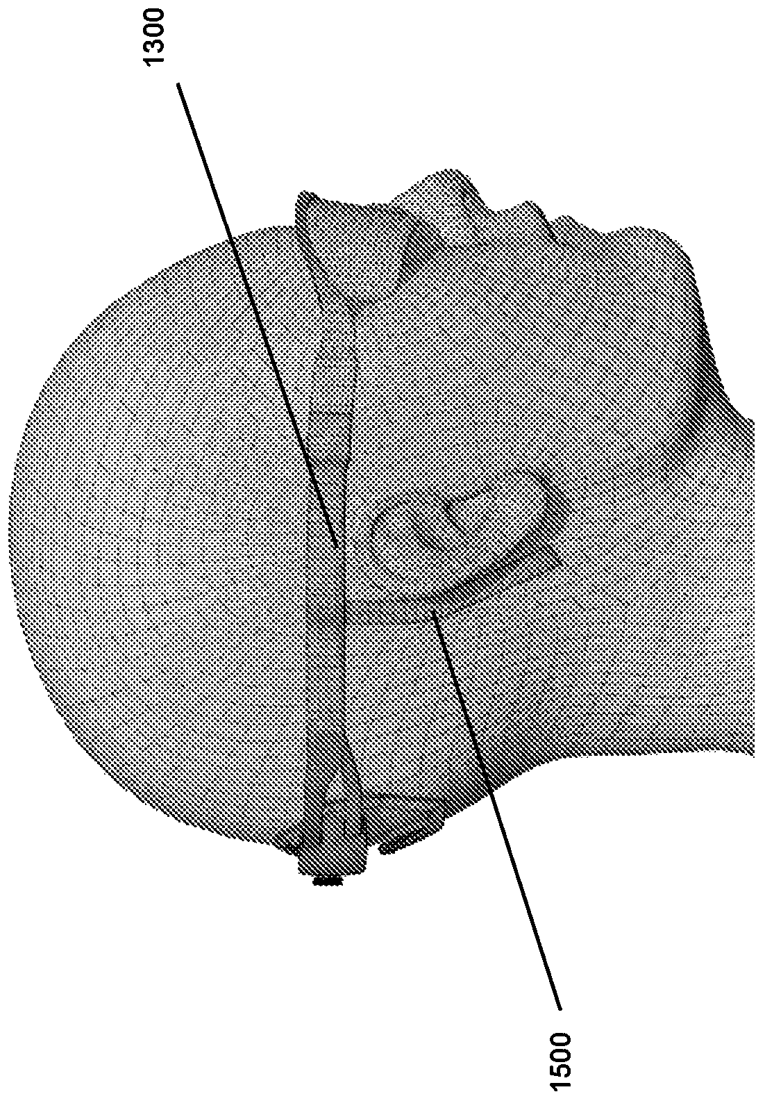
[0072] Referring now to the drawings, there is shown a head mounted device for detecting dysfunction of a patient's brain. Figure 1 to Figure 3 An embodiment of the device worn on the patient's head is shown. The device is configured to provide visual stimuli to the patient and to measure evoked potentials of the visual responses using a plurality of electrodes located near the skull overlying the patient's occipital lobe and on the surface of the skull. The occipital lobe is the part of the brain primarily responsible for visual processing.
[0073] Device 100 includes opaque goggles 1100 positioned over the patient's eyes. The goggles include an array of LEDs inside the goggles to which the patient's eyes are exposed (eg Figure 5 shown). The LEDs are arranged to provide visual stimulation to the patient when the device is activated. The device 100 comprises a housing 1200 arranged to be positioned at the back of the patient's head. Housing 1200 includes at least one e...
example 2
[0176] The goal of this study was to evaluate the utility of a portable electrophysiological platform for recording measurable SSVEP from healthy individuals.
[0177] participant
[0178] All participants were screened for seizures, convulsions, existing or previous brain injuries and conditions. Any positive result will exclude the participant from the study.
[0179] equipment
[0180] Two main components of the system were identified: the visual stimulus generation component and the EEG recorder. Data from the EEG recorder was captured using a computer and signal analysis was performed on the data. Visual stimuli were delivered in two separate settings: a portable smartphone setting, and another using a conventional LCD computer monitor. For a portable setup, a Sony Xperia Z1 Compact smartphone (Sony, Minato-ku, Tokyo, Japan) housed in a Google Cardboard (Google, Mountain View, CA, USA) was used. A Dell U2415 LCD monitor (Dell Technologies, One Dell Way, Round Rock, T...
example 3
[0251] In a further study, the aim was to evaluate the utility of the portable SSVEP platform in identifying concussions in rugby league players and identifying when they recover. A prospective cohort observational study was conducted during the season of rugby union training and game events. A total of 65 (age 20.9±2.3) athletes were enrolled in this study. Screening of athletes was performed to identify any contraindications to study participation and history of concussion. Tests are performed weekly during rugby club training.
[0252] The visual stimuli used in this study (see Figure 16A) were displayed as MP4 video files on a Sony Xperia Z1 Compact smartphone. The smartphone was placed in a Google Cardboard head kit, which participants held on their head and covered their eyes. The MP4 video consists of a series of black and white screens alternating at 15Hz. A figure was placed in the middle of the screen (within 2% of the screen, with a viewing angle of 1.5°) to all...
PUM
 Abstract
Description
Claims
Application Information