Agricultural pest killing device

An operating device and agricultural technology, applied in the field of agricultural insecticide, can solve the problems of short service life, long maintenance time and high repair rate, and achieve the effects of avoiding the spread of insect pests, good insect attracting effect and protecting the environment.

Inactive Publication Date: 2019-12-27
孙丽涛
View PDF0 Cites 1 Cited by
  • Summary
  • Abstract
  • Description
  • Claims
  • Application Information

AI Technical Summary

Problems solved by technology

Arranging insecticidal lights in the field requires the laying of transmission lines and consumes a lot of electricity, which increases the cost of agricultural production
Existing insecticidal lamps have large technical bottlenecks that need to be solved urgently, and their service life is short. The service life of ordinary insecticidal lamps is about 1 year, and the failure rate is high, and the repair rate is high
It takes a long time to maintain the machine, and it is troublesome for the farmers to maintain it themselves. To a certain extent, it will damage the production of the farmers and easily cause mis-cultivation. Farmers generally find it difficult to accept insecticidal lamps and consume a lot of power. The current daily power consumption of insecticidal lamps is relatively large. , even more than 2-3 times the average daily electricity consumption of farmers, and the efficiency of electricity consumption is low, resulting in waste of electricity energy, directly increasing the economic burden of farmers, resulting in an increase in the indirect cost of insecticide

Method used


Image

  • Agricultural pest killing device
  • Agricultural pest killing device

Examples


Embodiment Construction

[0016] The present invention will be further described below in conjunction with specific examples. It should be understood that these examples are only used to illustrate the present invention and are not intended to limit the scope of the present invention. In addition, it should be understood that after reading the teachings of the present invention, those skilled in the art can make various changes or modifications to the present invention, and these equivalent forms also fall within the scope defined by the appended claims of the application.

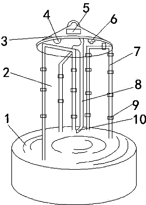
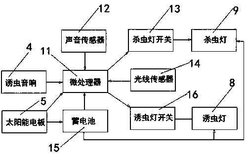
[0017] see figure 2 It is a structural diagram of the control principle of the present invention, and the present invention includes an insect baffle 2, a rain cover 3, an insect trap 6, a frame 7, an insect trap 8, an insect-killing lamp 9, a microprocessor 11, a sound sensor 12, and an insect-killing lamp Switch 13, light sensor 14, accumulator 15, trap light switch 16, microprocessor 11 is connected with sound sensor 12, insect...


PUM


Abstract

The invention relates to the technical field of agricultural pest killing, in particular to an agricultural pest killing device. The agricultural pest killing device is characterized in that a microprocessor is connected with a sound sensor, a pest killing lamp switch, a light sensor and a pest luring lamp switch, the pest killing lamp switch is connected with pest killing lamps, the pest luring lamp switch is connected with a pest luring lamp, the pest killing lamps are arranged on a frame, a pest blocking plate is arranged outside the frame, a rain cover is arranged at the top end of the frame, the pest luring lamp vertical to the rain cover is arranged at the bottom of the rain cover, a rubber ring is arranged at the bottom of the pest luring lamp, and a pest luring loudspeaker is arranged at the bottom of the rain cover. The agricultural pest killing device has the advantages that pests are lured through the pest luring lamp, a pest luring bag and the pest luring loudspeaker, different agricultural pests can be lured and killed, and a good pest luring effect is achieved by the various pest luring methods; the microprocessor is used to control the on and off of the pest killinglamps and the pest luring lamp, the pest killing lamp switch is controlled by the sound sensor to save power, a storage battery is charged by a solar panel to power the whole device, energy saving andenvironmental protection are achieved, the killed agricultural pests are recovered through a basin at the bottom of the device, environments are protected, and pest spreading is avoided.

Description

technical field [0001] The invention relates to the technical field of agricultural insecticide, in particular to an agricultural insecticide operation device. Background technique [0002] For a long time, in order to protect crops from pests, chemical pesticides have been widely used. However, the abuse of chemical pesticides has caused serious pesticide residues in crops to exceed the standard, affecting human health and causing environmental pollution. At the end of the last century, people studied the use of physical methods for pest control, that is, using the characteristics of insects such as phototaxis, color, taste, and sex to trap and kill insects. Among them, the research on insecticidal lamp trapping and killing insects using the phototaxis of insects is the earliest and the most mature technology. The lamps set the wavelength and intensity that the pests like, and lure the pests to the vicinity of the lamps, causing the compound eye effect to dazzle the lamps...

Claims


Application Information

Patent Timeline
Patent Type & Authority Applications(China)
IPC IPC(8): A01M1/22A01M1/02A01M1/04
CPCA01M1/02A01M1/023A01M1/04A01M1/226
Inventor 孙丽涛
Owner 孙丽涛
Why Eureka
Try Eureka