
Computed tomography apparatus and method for determining its sliding contact operating state

A sliding contact, tomography technology, used in computer tomography scanners, instruments for radiological diagnosis, diagnosis, etc., can solve problems such as high maintenance costs

Active Publication Date: 2021-05-11
SIEMENS HEALTHCARE GMBH
View PDF5 Cites 0 Cited by
  • Summary
  • Abstract
  • Description
  • Claims
  • Application Information

AI Technical Summary

Problems solved by technology

This leads to unnecessarily high maintenance costs, since this also replaces sliding contacts whose wear is still tolerable

Method used


Image

  • Computed tomography apparatus and method for determining its sliding contact operating state
  • Computed tomography apparatus and method for determining its sliding contact operating state
  • Computed tomography apparatus and method for determining its sliding contact operating state

Examples


Embodiment Construction

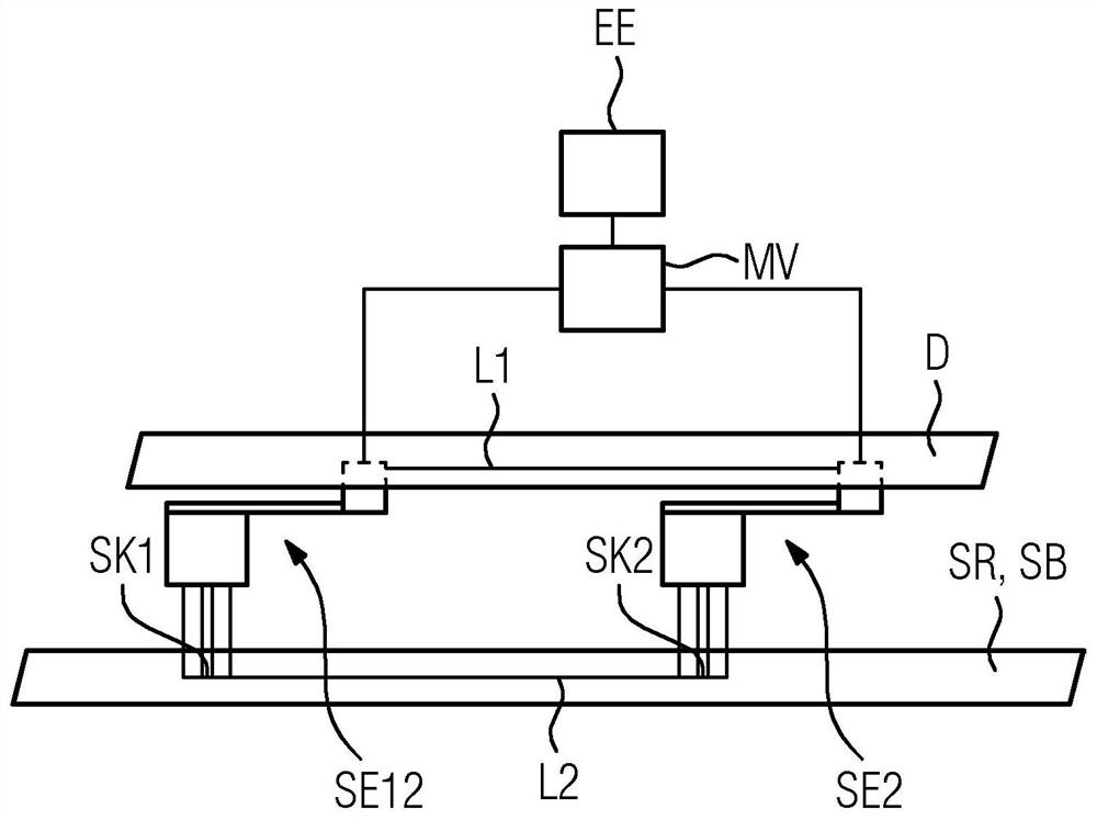
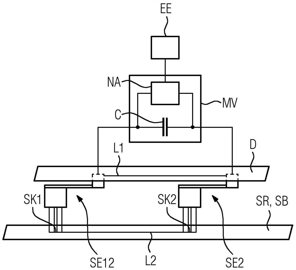
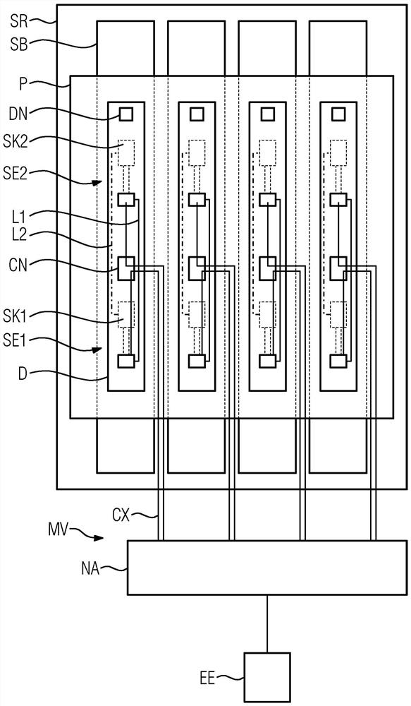
[0064] figure 1 Shown is a slip ring SR with a sliding track SB, a power supply line D, sliding contact elements SE1 and SE2, sliding contacts SK1 and SK2, a measuring device MV and a determination unit EE. The slip ring SR has a slide track SB and is rotatable relative to the feeder D. At the feed line D, two sliding contact elements SE1 and SE2 are arranged. Each of the two sliding contact elements SE1 and SE2 is designed as a brush, for example a carbon brush.

[0065] Each of the two sliding contact elements SE1 and SE2 is connected to the feeder D by means of a spring element and a contact pressure adjustment device, wherein the contact pressure adjustment device is designed to adjust the contact pressure of the brush on the sliding rail SB. One end of the spring element is fixedly connected to the feeder D. The other end of the spring element is fixedly connected to the brush. The spring element can have, for example, an elastic metal strip which is clamped in the re...


PUM


Abstract

The invention relates to a computed tomography apparatus with: - a slip ring for rotational transmission, - a feed line, wherein the slip ring is arranged rotatably relative to the feed line, - two sliding contact elements, which slide Sliding contact is formed between the sliding track of the ring and the feeder line and are communicated in parallel with each other, so that the two sliding contact elements are electrically conductively connected to each other by means of at least one section of the slide track and by means of at least one section of the feeder line, the measurement a device designed to detect a measured value, which depends on the inductance generated between the two sliding contact elements, and a determination unit designed to determine the operating state of the sliding contact based on the measured value.

Description

technical field [0001] The invention relates to a computed tomography system and a method for determining the operating state of a sliding contact on a slip ring for rotational transmission in a computed tomography system. Background technique [0002] For rotational transmission in computed tomography systems, slip rings with one or more sliding contacts are often used. The sliding contact can be realized, for example, in the form of carbon and / or brushes. Abrasion, contamination and / or special stresses can cause sliding contacts to fail. A failed sliding contact can cause arcing, which can damage the slip ring and, in particular, can lead to an interruption of inspections by means of computed tomography equipment. As the sliding contacts wear over time, they must be replaced periodically. [0003] In general, damage to the sliding rails caused by arcing is avoided by replacing the sliding contacts very early. This leads to unnecessarily high maintenance costs, since th...

Claims


Application Information

Patent Timeline
Patent Type & Authority Patents(China)
IPC IPC(8): A61B6/03A61B6/00
CPCA61B6/035A61B6/44A61B6/52A61B6/032A61B6/56A61B6/586A61B6/58G01R27/2611G01R27/28H01R39/26
Inventor B·格贝特M·克劳斯
Owner SIEMENS HEALTHCARE GMBH
Learn More