Multi-degree-of-freedom lower limb rehabilitation robot

A technology of rehabilitation robot and degree of freedom, which is applied in the direction of equipment for compressing reflex points, equipment for helping people walk, physical therapy, etc. Effect

Inactive Publication Date: 2019-12-27
MBZ TIANJIN REHABILITATION EQUIP CO LTD
8 Cites 0 Cited by

AI-Extracted Technical Summary

Problems solved by technology

[0004] The purpose of the present invention is to provide a multi-degree-of-freedom lower limb rehabilitation robot to solve ...

Abstract

The invention discloses a multi-degree-of-freedom lower limb rehabilitation robot. The multi-degree-of-freedom lower limb rehabilitation robot comprises a lower limb rehabilitation robot main body; afoot supporting plate is arranged at the bottom of the lower limb rehabilitation robot main body; a round hole is formed at the top of the foot supporting plate; a disk is arranged in the round hole;a bead is arranged at the top of the disk; the bottom of the disk is connected with a supporting shaft; the supporting shaft is positioned in a cavity in the middle of the foot supporting plate; a worm wheel is arranged outside the supporting shaft in a sleeving way; one side of the worm wheel is in engaged connection with a worm; one end of the worm is connected with the inner wall of one side ofthe cavity, and the other end of the worm passes through the side wall of the back end of the foot supporting plate and is connected with a motor; and a gasket is arranged at the top of the foot supporting plate. According to the multi-degree-of-freedom lower limb rehabilitation robot, the structures such as the disk and the bead cooperate with the foot supporting plate, and the foot supporting plate has a massage function, so that the lower limb rehabilitation robot can massage feet of a patient to dredge blood circulation while assisting in walking action, and can meet requirements.

Application Domain

Technology Topic

Image

  • Multi-degree-of-freedom lower limb rehabilitation robot
  • Multi-degree-of-freedom lower limb rehabilitation robot
  • Multi-degree-of-freedom lower limb rehabilitation robot

Examples

  • Experimental program(2)

Example Embodiment

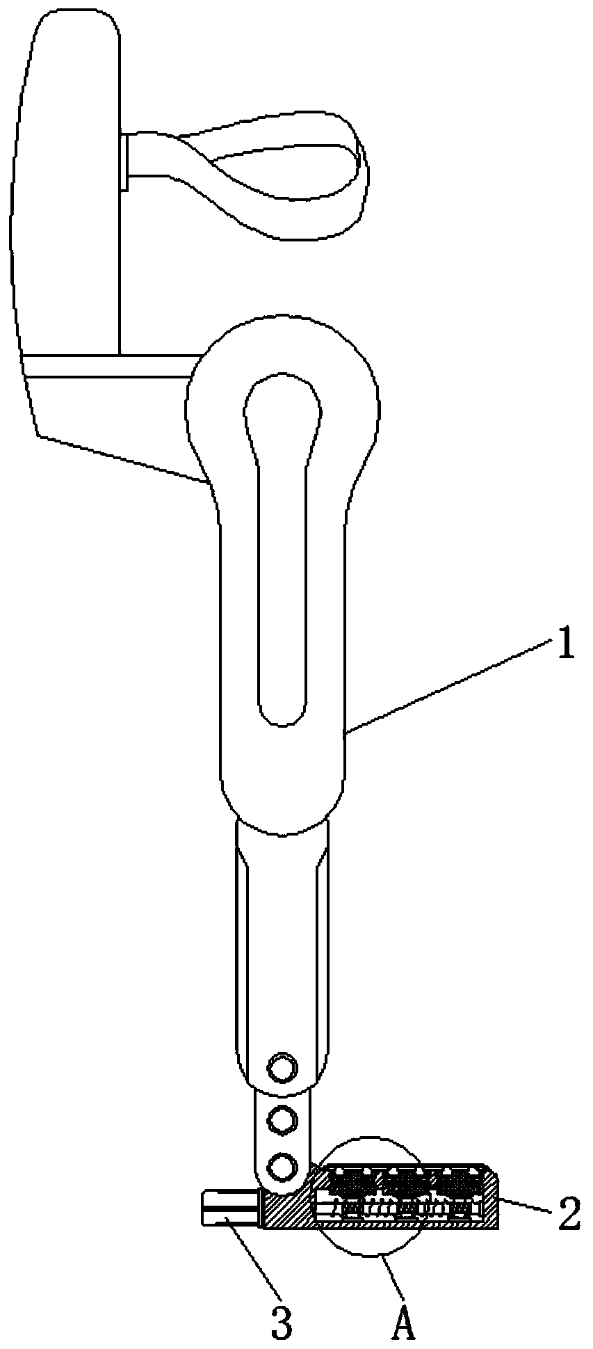
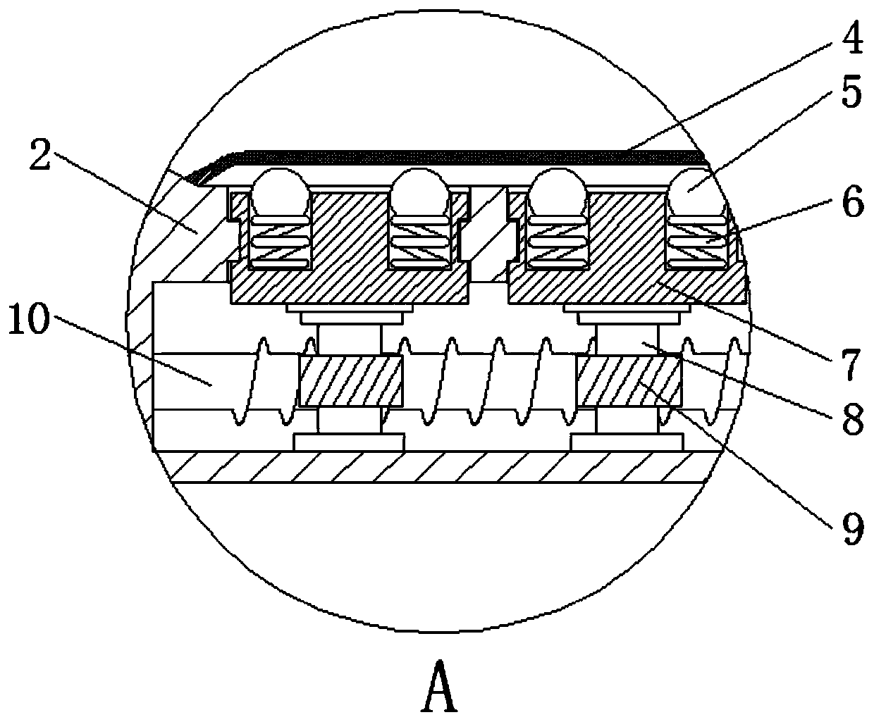
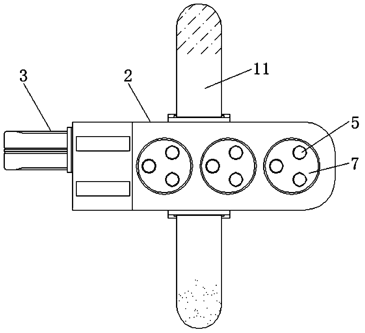
[0019] Embodiment 1: A lower limb rehabilitation robot with multiple degrees of freedom, comprising a lower limb rehabilitation robot main body 1, a foot support plate 2 is arranged at the bottom of the lower limb rehabilitation robot main body 1, and the foot support plate 2 is hinged with the lower end of the lower limb rehabilitation robot main body 1, and the feet The top of the support plate 2 is provided with a round hole, and a disc 7 is arranged in the round hole, and the disc 7 is connected to the round hole for rotation, and the top of the disc 7 is provided with a ball 5, and the ball 5 is driven by the disc 7 The rotation can have a massage effect on the angle of the patient. A cylindrical groove is provided on the disc 7, and the ball 5 is located in the cylindrical groove, and the ball 5 is slidably connected with the inner wall of the cylindrical groove, and the ball 5 The bottom is connected with the upper end of the compression spring 6, the lower end of the compression spring 6 is connected with the bottom edge of the cylindrical hole, and the two ends of the compression spring 6 respectively stand on the bottom edge of the ball 5 and the cylindrical hole, so that the ball 5 has elasticity , so as to form a more comfortable massage for the patient. The diameter of the top opening of the cylindrical hole is smaller than the diameter of the ball 5. This structure makes the ball 5 inseparable. The cylindrical hole, and the top of the ball 5 protrudes from the cylindrical hole. So that the ball 5 can stand on the sole of the patient's foot, there are multiple disks 7 on the top of the foot support plate 2, and multiple balls 5 are arranged around the top of the disk 7, the number of disks 7 and balls 5 like image 3 As shown in , this structure can massage the patient's soles more evenly, so as to be more comprehensive. An annular groove is arranged on the outer wall of the disc 7, and an annular protrusion is arranged on the inner wall of the round hole on the foot support plate 2. The annular protrusion The structure of the ring groove is matched with the structure of the ring groove. Through the restriction of the ring groove to the ring protrusion, the disc 7 can rotate stably in the round hole on the foot support plate 2. The bottom of the disc 7 is connected with a support shaft 8, which supports The shaft 8 is welded with the disc 7, the support shaft 8 is located in the cavity in the middle of the foot support plate 2, the lower end of the support shaft 8 is connected to the bottom of the cavity in rotation, and the support shaft 8 is covered with a worm wheel 9, and the worm wheel 9 is connected to the bottom of the cavity. The support shaft 8 is fixed by clamping, and one side of the worm wheel 9 is meshed with a worm 10. This structure enables the disk 7 to be rotated by the worm 10. One end of the worm 10 is connected to the inner wall of one side of the cavity, and here through the bushing Rotationally connected, and the other end of the worm 10 is connected through the rear end side wall of the foot support plate 2, the motor 3 and the worm screw 10 are connected through a coupling, and the motor 3 and the foot support plate 2 are fixed by screw connection, this structure makes Worm screw 10 can be rotated by motor 3, thereby can realize automatic massage, and the top of foot support plate 2 is provided with spacer 4, and the peripheral edge of spacer 4 is connected with the surrounding edge of foot support plate 2, and spacer 4 is connected with foot support plate 2. It is connected by sewing. The gasket 4 can be made of soft cotton cloth, which is more comfortable when the cotton cloth is in contact with the patient's skin. The two sides of the foot support plate 2 are respectively provided with straps 11, and one end of one of the straps 11 is provided with a nylon strap. Buckle the adhesive surface, and one end of the other strap 11 is provided with a Velcro lower adhesive surface, and the strap 11 is connected with the foot support plate 2 by sewing, and this structure can easily connect the foot support plate 2 with the foot.

Example Embodiment

[0020] Embodiment 2: The gasket 4 can be made of leather, which is easier to clean.
[0021] Working principle: When using the multi-degree-of-freedom lower limb rehabilitation robot, first check whether the device is damaged or not connected firmly, and then use it after checking, and tie the patient's leg to the lower limb rehabilitation robot through straps On the main body 1, the sole of the patient's foot rests on the top of the foot support plate 2. When a foot massage is required, the motor 3 is started, and the motor 3 drives the connected worm 10 to rotate, and the worm 10 drives the worm gear 9 to rotate. The support shaft 8 is fixedly connected, and the support shaft 8 is fixedly connected with the disk 7, so that the disk 7 can be driven to rotate together. The disk 7 is provided with a ball 5, so that the ball 5 is driven to rotate, and the ball 5 protrudes from the foot. The top of the support plate 2 enables the patient's feet to be in contact with the ball 5, so that the rotating ball 5 can massage the patient's bottom and promote the patient's blood circulation, thereby better meeting people's needs. The working principle of the lower extremity rehabilitation robot with degrees of freedom.

PUM

no PUM

Description & Claims & Application Information

We can also present the details of the Description, Claims and Application information to help users get a comprehensive understanding of the technical details of the patent, such as background art, summary of invention, brief description of drawings, description of embodiments, and other original content. On the other hand, users can also determine the specific scope of protection of the technology through the list of claims; as well as understand the changes in the life cycle of the technology with the presentation of the patent timeline. Login to view more.

Similar technology patents

Classification and recommendation of technical efficacy words

Why Eureka
Try Eureka