
Detecting and calibrating platform for capping head of capping machine

A technology of capping machine and capping head, which is applied to the safety/control of bottle capping machines and flanged bottle caps, etc. It can solve the problems of time-consuming, laborious, manpower, and unfavorable safety production, so as to improve economic benefits and safety. High, the effect of improving work efficiency and production capacity

Pending Publication Date: 2019-12-27
高战
View PDF0 Cites 2 Cited by
  • Summary
  • Abstract
  • Description
  • Claims
  • Application Information

AI Technical Summary

Problems solved by technology

Such a detection method not only wastes manpower, but also has uncertain pressure. During the detection process, it is easy to cause dangers such as bottle bursting.

Method used


Image

  • Detecting and calibrating platform for capping head of capping machine
  • Detecting and calibrating platform for capping head of capping machine
  • Detecting and calibrating platform for capping head of capping machine

Examples


Embodiment 1

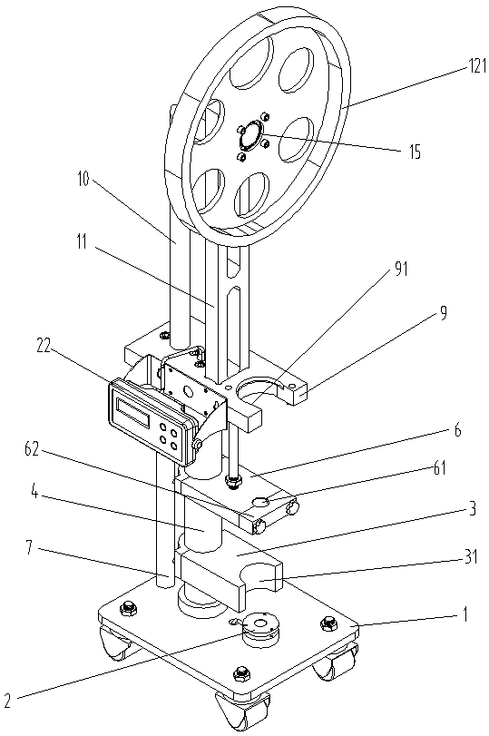
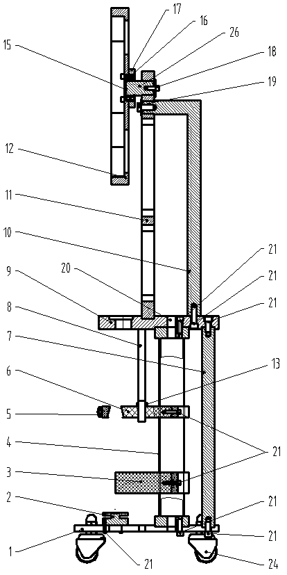
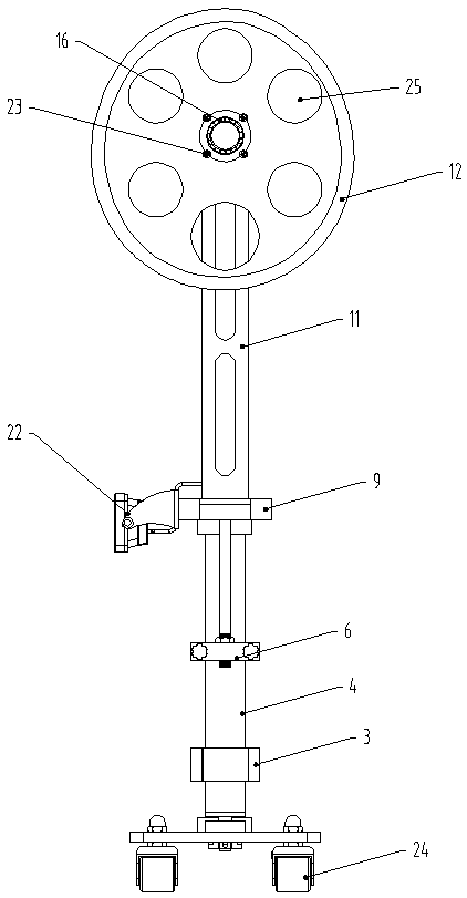
[0024] Such as figure 1 , 2 . The capping machine capping head inspection and verification platform shown in 3 is used to detect the pressure of the spring in the capping machine and the accuracy of the capping, including a cam 12, a base 1, a support plate 9, and a bearing structure 15. A central support tube 4 and a first pillar 7 are provided between the base 1 and the support plate 9, a bracket 11 and a pole 10 are arranged on the support plate 9 in sequence, and a weighing display controller is provided on one side of the support plate 9 22. The front end of the support plate 9 is provided with a clamping position 91 for fixing the capping machine; the cam 12 is fixed on the upper end of the bracket 11 through the bearing structure 15, the rear end of the bearing structure 15 is fixed on the bracket 11, and the front end is fixed on the On the cam 12, the bearing structure 15 includes a bearing 16, a bearing washer 17, and a bearing column 26. The bearing 16 is fixed on ...

Embodiment 2

[0032]On the basis of not changing other structures, the bearing structure can also be a concentric circle structure with the cam, that is, the bearing is installed at the center of the cam, and the thickness of the ring wall of the cam is different, which is a change from narrow to thick. When the cam and the gland When the machine contact position reaches the narrowest end, the capping head is lifted, and the wall thickness of the rotating cam ring gradually changes from narrow to thick. The capping head moves downward with the increase of the ring wall thickness and finally reaches the thickest end of the ring wall. When the capping head touches the simulated bottle, so as to obtain a pressing force, and measure the pressure of the capping machine.


PUM


Abstract

The invention relates to the technical field of filling device, and discloses a detecting and calibrating platform for a capping head of a capping machine. The detecting and calibrating platform is used for detecting the pressure and precision of the capping machine, and comprises a cam, a base, a supporting plate, a bearing structure, a central supporting pipe, a first supporting column, a support and a supporting rod. The cam is fixed to the upper end of the support through the bearing structure. The rear end of the bearing structure is fixed to the support. The front end of the bearing structure is fixed to the cam. The circle center of the bearing structure and the circle center of the cam are located on the same straight line without being overlapped together. A bottle neck protectionplate and a bottle body protection plate are arranged on the central supporting pipe. A gravity sensor where a bottle body can be placed is arranged on the upper side of the base. Whether the cappinghead of the capping machine is precise or not can be rapidly and effectively judged, the problems that the bottle explosion is caused by the too large pressure of the capping machine and the air leakage of a bottle cap is caused by the small pressure are effectively solved, meanwhile whether the cap deviation problem exists or not can be detected, no too much artificial interference is needed, time and labor are saved, safety is high, work efficiency and production capacity can be effectively improved, and therefore economic benefits are improved.

Description

technical field [0001] The invention relates to the technical field of filling equipment detection, in particular to a capping head detection and verification platform of a capping machine. Background technique [0002] Capping machine is an integral part of packaging machinery and an indispensable link of packaging machinery. The efficiency of the capping machine will inevitably affect the efficiency of the entire packaging machinery. If there is no capping machine automatically controlled by high-efficiency modern machinery, then the packaging machinery will not be able to develop rapidly. At present, the capping method commonly used by the capping machine is to use springs or cylinders for capping. This capping method not only has a relatively large error range of pressure, but also cannot detect the magnitude of the pressure, let alone control it. It is very difficult to adjust the capping force, and it is easy to cause the bottle to burst due to excessive pressure, or ...

Claims


Application Information

Patent Timeline
IPC IPC(8): B67B3/26B67B3/10
CPCB67B3/26B67B3/10Y02E60/10
Inventor 高战
Owner 高战
Learn More