
The lowering method of the steel casing

A steel casing and steel platform technology, applied in construction, foundation structure engineering, sheet pile walls, etc., can solve the problems of increased cost and high rental cost of large-scale hoisting equipment, and achieve the effect of increasing hoisting capacity

Active Publication Date: 2022-04-15
CCFEB CIVIL ENG
View PDF3 Cites 0 Cited by
  • Summary
  • Abstract
  • Description
  • Claims
  • Application Information

AI Technical Summary

Problems solved by technology

If large-scale hoisting equipment is used to meet hoisting requirements, since large-scale hoisting equipment is relatively rare, and the rental cost of large-scale hoisting equipment is high, in addition, the use of large-scale hoisting equipment will increase the load of the water construction platform, and the water construction platform needs to be reinforced. Therefore The use of large hoisting equipment will greatly increase the cost

Method used


Image

  • The lowering method of the steel casing
  • The lowering method of the steel casing
  • The lowering method of the steel casing

Examples


no. 1 example

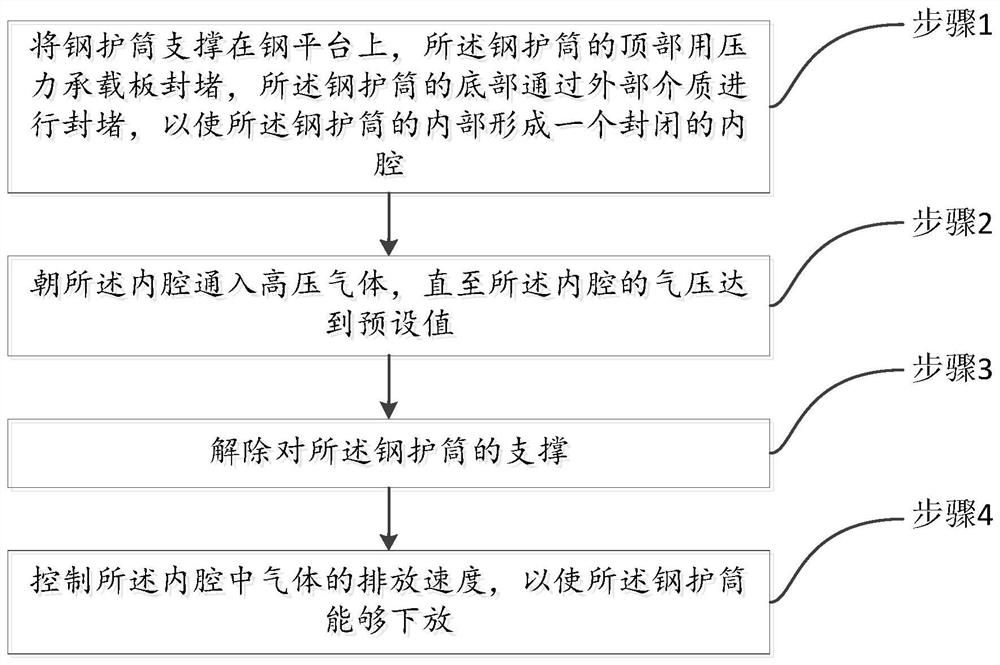
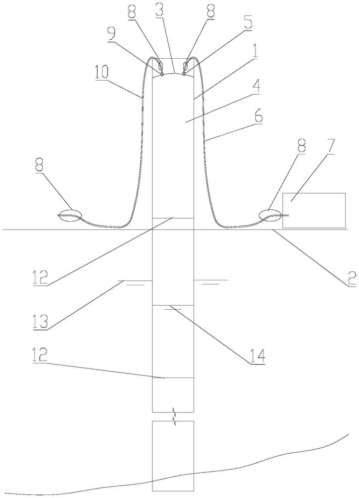
[0044] Please refer to figure 1 and figure 2 , the present embodiment provides a method for lowering the steel casing 1, which includes the following steps:

[0045] Step 1, supporting the steel casing 1 on the steel platform 2, the top of the steel casing 1 is sealed with a pressure bearing plate 3, and the bottom of the steel casing 1 is blocked by an external medium, so that the A closed cavity 4 is formed inside the steel casing 1 .

[0046] The method provided in this embodiment is used to lower the steel casing 1. First, the steel casing 1 needs to be supported on the steel platform. The specific support method can be that the steel casing 1 is directly welded on the steel platform 2, or it can be connected A support 11 welded on the steel platform 2 is fixedly connected; after the steel casing 1 is supported on the steel platform 2, the end near the top of the steel platform 2 is the top of the steel casing 1, and the end near the bottom of the steel platform 2 It i...

no. 2 example

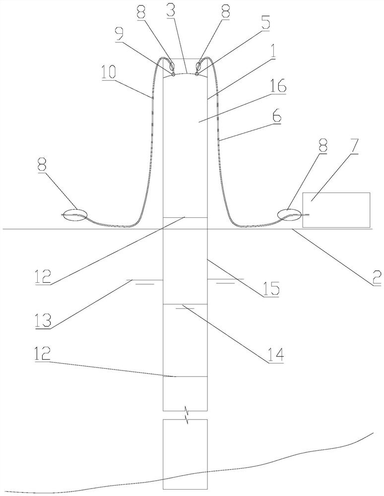
[0075] Please refer to image 3 , the present embodiment provides a method for lowering a steel casing, which is applied to lowering a multi-section steel casing by a crane with limited lifting capacity. Assuming that the lifting capacity of the crane is n steel casings, the first n steel casings are lowered in the original way, and the first embodiment is adopted from the n+1th steel casing 16 to the n+ith steel casing The method for lowering the steel casing is provided, so the method for lowering the steel casing in the first embodiment also belongs to this embodiment, and will not be repeated here.

[0076] The lowering method of the front n section steel casing comprises the following steps:

[0077] Step 1, measurement and setting out: accurately set out the position of the steel casing on the steel platform 2.

[0078] Step 2, install the guide frame: fix the guide frame on the steel platform 2.

[0079] Step 3, lowering the first section of steel casing: the first s...


PUM


Abstract

The invention provides a method for lowering a steel casing and relates to the technical field of steel casing hoisting. The method includes: step 1, supporting the steel casing on a steel platform, the top of the steel casing is sealed with a pressure bearing plate, and the bottom of the steel casing is blocked by an external medium, so that the inside of the steel casing forms a Closed lumen; step 2, pass gas into the lumen until the air pressure in the lumen P 1 Reach the preset value; step 3, release the support to the steel casing; step 4, control the discharge speed of the gas in the inner cavity, so that the steel casing can be lowered. The lowering method of the steel casing adopted in the present invention is to form a closed cavity inside the steel casing by closing the two ends of the steel casing, and then pass the gas in the cavity until P i When the preset value is reached, the pressure bearing plate on the top of the steel casing is under upward pressure, which can offset part or all of the gravity of the steel casing itself, thereby increasing the hoisting capacity of the hoisting equipment.

Description

technical field [0001] The invention relates to the technical field of steel casing hoisting, in particular to a method for lowering a steel casing. Background technique [0002] Existing cranes have limited hoisting capacity, which can only meet the hoisting of a certain number of steel casings. If large-scale hoisting equipment is used to meet hoisting requirements, since large-scale hoisting equipment is relatively rare, and the rental cost of large-scale hoisting equipment is high, in addition, the use of large-scale hoisting equipment will increase the load of the water construction platform, and the water construction platform needs to be reinforced. Therefore The use of large lifting equipment will greatly increase the cost. Contents of the invention [0003] The object of the present invention is to provide a method for lowering a steel casing, which can reduce the hoisting pressure of the hoisting equipment and reduce the hoisting cost. [0004] Embodiments of t...

Claims


Application Information

Patent Timeline
Patent Type & Authority Patents(China)
IPC IPC(8): E02D7/00
CPCE02D7/00
Inventor 何威特彭云涌肖超胡力董小兵
Owner CCFEB CIVIL ENG
Learn More