Assembly and container system for pressurized fluids and its manufacturing method and device

A pressurized fluid and container technology, applied in the installation device of the container structure, the manufacture of the container structure, the geometry/arrangement/size of the container structure, etc., can solve the problem of not having burst resistance

Inactive Publication Date: 2003-04-30
ECC SYST
View PDF2 Cites 0 Cited by
  • Summary
  • Abstract
  • Description
  • Claims
  • Application Information

AI Technical Summary

Problems solved by technology

Containers of synthetic plastics are also currently used as containers for pressurized fluids, however existing containers of this type do not have sufficient burst strength when encountering high fluid pressures

Method used


Image

  • Assembly and container system for pressurized fluids and its manufacturing method and device
  • Assembly and container system for pressurized fluids and its manufacturing method and device
  • Assembly and container system for pressurized fluids and its manufacturing method and device

Examples


Embodiment Construction

[0026] Detailed description of the preferred embodiment

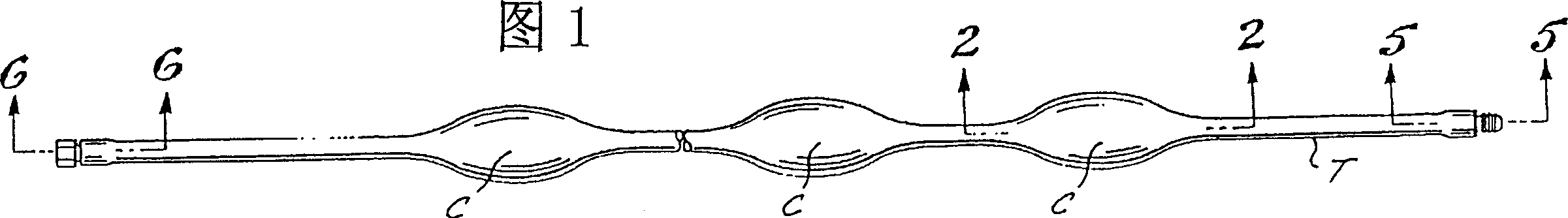
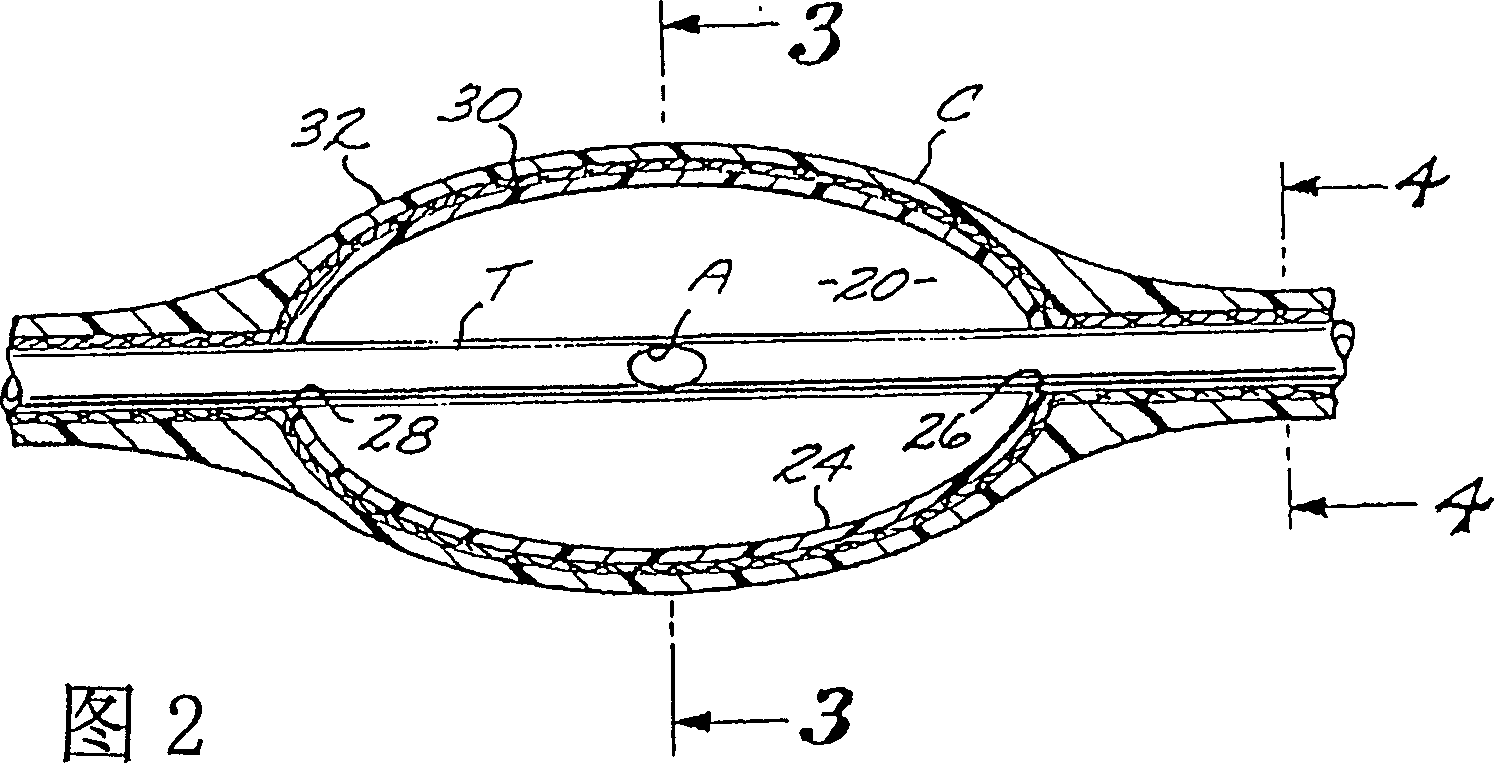
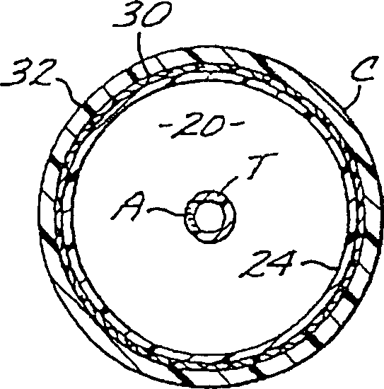
[0027] Referring to the drawings, and in particular FIGS. 1-6, a pressurized vessel system embodying the invention includes a plurality of conformal, generally elliptical chambers C and tube cores T coaxially and hermetically secured to the chambers. C on. The die T is provided with a plurality of longitudinally equidistantly spaced holes A which communicate with the fluid conveyed within the interior 20 of each cavity C along its length. The size of the holes A is selected to control the rate of discharge of the pressurized fluid from the chamber C such that a very low rate of fluid discharge can be produced thereby avoiding large and potentially energy leaks when one or more chambers C are perforated, explosion occurs.

[0028] Referring now to Figures 2 and 3, each chamber C includes a generally oval shell 24 molded from a suitable synthetic plastic having open front and rear ends 26 and 28 . Holes 26 and 28 are s...


PUM


Abstract

A container system for pressurized fluids that includes a plurality of generally ellipsoidal chambers connected by a tubular core. The tubular core is formed along its length with a plurality of apertures each of which is positioned within one of the chambers. The apertures are of comparatively small size so as to be able to control the rate of evacuation of pressurized fluid should a chamber be ruptured.

Description

field of invention [0001] The present invention relates to containers for pressurized fluids, which results in an inexpensive, light, dense, flexible, safe and burst-resistant container for pressurized fluids, the present invention also relates to assemblies for pressurized fluids and container systems and methods and apparatus for making the same. Background of the invention [0002] Today's containers for the storage and use of pressurized fluids, especially gases, generally employ cylindrical metal bottles wrapped with reinforcing material to resist high fluid pressures. Such storage devices are expensive to manufacture, heavy and bulky, inflexible and prone to rupture, which can lead to explosions. Such containers are commonly used to store oxygen, and the medical use of compressed oxygen for ambulatory patients is growing rapidly. Another example is the portable metal canisters carried by firefighters to provide emergency gas in the event of a fire. Synthetic plastic...

Claims


Application Information

Patent Timeline
Patent Type & Authority Patents(China)
IPC IPC(8): B29C65/08B67D7/78F17C1/00F17C1/16
CPCF17C2203/0619F17C2203/0673F17C2209/2145F17C2209/2127F17C2203/0663F17C2203/0621F17C2201/056F17C2205/0358F17C2205/0138F17C2260/042F17C2221/011F17C2205/0115F17C2270/0105F17C2201/058F17C2221/031F17C2201/054F17C2203/0607F17C2209/2118F17C2205/0397F17C2270/0189F17C2203/066F17C2209/2154F17C2209/232F17C2270/0178F17C1/00F17C2201/0138F17C2209/221F17C2205/0364F17C1/16F17C2221/014F17C2205/0165F17C2223/0123F17C2201/032B67D7/78
Inventor 斯坦·A·桑德斯
Owner ECC SYST
Why Eureka
Try Eureka