
A kind of mechanical processing waste material collection device
A waste material and collection device technology, applied in metal processing equipment, metal processing machinery parts, manufacturing tools, etc., can solve problems such as poor buffer protection effect, and achieve the effect of good elasticity and good buffer effect
- Summary
- Abstract
- Description
- Claims
- Application Information
AI Technical Summary
Problems solved by technology
Method used
Image

Examples
Embodiment
[0092] In order to make the technical means, creative features, goals and effects achieved by the present invention easy to understand, the present invention will be further elaborated below in conjunction with illustrations and specific embodiments.
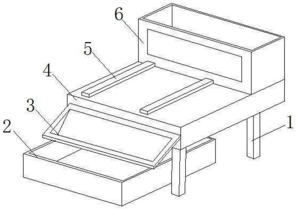
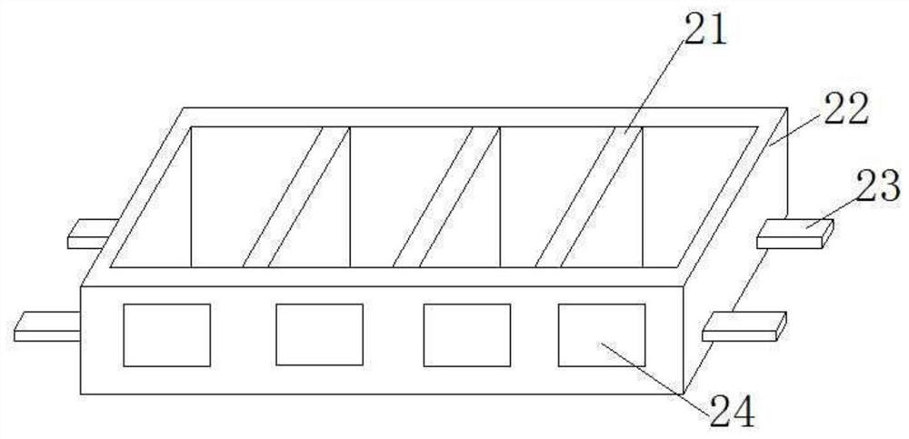
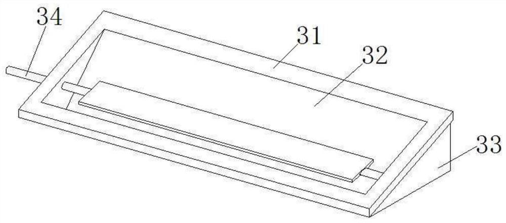
[0093] combine Figure 1 to Figure 13 The mechanical processing waste material collection device of the present invention is described in detail.
[0094] The mechanical processing waste material collecting device of the present embodiment includes a support leg 1, the support leg 1 is in the shape of a cuboid, and the frame 4 is in the shape of a cuboid, and the frame 4 is fixed on the upper end of the support leg 1 with bolts. The collection box 2 is installed under the frame 4 , and the collection box 2 slides under the frame 4 along the length direction of the frame 4 . The guide frame 3 is pivotally connected to the end of the frame 4 , and the guide frame 3 is placed above the collection box 2 , and the lower edge of the ...
PUM
 Abstract
Description
Claims
Application Information