

Lung function training device for respiratory medicine department
A respiratory medicine and training device technology, applied in sports accessories, gymnastics equipment and other directions, can solve the problems of complex display display, inability to objectively control training intensity by patients, troublesome operation, etc., and achieves convenient observation, convenient placement and efficient training effect Effect
- Summary
- Abstract
- Description
- Claims
- Application Information
AI Technical Summary
Problems solved by technology
Method used
Image

Examples
Embodiment
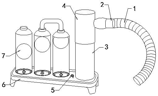
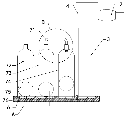
[0028] see Figure 1-Figure 3 , the present invention provides a pulmonary function training device for respiratory medicine, its structure includes a telescopic breathing tube 1, a connecting small tube 2, an air intake tube 3, a connecting tube 4, a control valve 5, a chassis 6, a ladder display system 7, and the chassis 6 The top surface is provided with a ladder display system 7, and an air intake pipe 3 is installed on the chassis 6 on one side of the ladder display system 7, and a control valve 5 is arranged between the air intake pipe 3 and the ladder display system 7, and the top of the air pipe 3 A connecting tube 4 is provided, and the connecting tube 4 and the trachea 3 are connected together. A small connecting tube 2 is installed horizontally on the side of the connecting tube 4, and a telescopic breathing tube 1 is nested at the end of the connecting small tube 2. Tube 1 is connected to the patient's oral cavity.
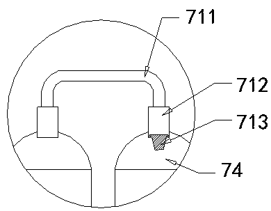
[0029] The ladder display system 7 is provided ...
PUM
 Abstract
Description
Claims
Application Information