Medical waste crushing and sterilizing cabinet

A technology for medical waste and sterilization cabinets, which is applied to grain processing, sanitary equipment for toilets, water supply devices, etc. High safety and operation stability, improve sterilization effect and processing efficiency, and ensure the effect of sterilization effect

Pending Publication Date: 2019-12-31
JIANGSU SHENNONG AUTOCLAVE
View PDF9 Cites 2 Cited by
  • Summary
  • Abstract
  • Description
  • Claims
  • Application Information

AI Technical Summary

Problems solved by technology

The disadvantages of this kind of sterilization first and then crushing are: 1) the sterilization effect is not good, especially when there is a lot of medical waste, it is difficult for the steam to penetrate all the medical waste; 2) agglomeration during the sterilization process affects the subsequent discharge , the normal operation of the conveying and crushing process
Due to the following disadvantages in the currently used sterilizers: (1) The sterilizer does not have the function of crushing medical waste, and it is impossible to sterilize while crushing inside the sterilizer, which greatly affects the sterilization effect and quality of medical waste. Processing efficiency; (2) The locking mechanism of the cabinet door of the sterilizing cabinet is shown in the "A Cabinet Door Locking Device" disclosed in the invention patent with the application number: 201721846403.3, but this cabinet door locking device is inconvenient to operate. The locking effect on the cabinet door is poor, and the use safety and stability are poor. The high-pressure steam in the sterilization cabinet is easy to open the cabinet door, which affects the sterilization efficiency.

Method used


Image

  • Medical waste crushing and sterilizing cabinet
  • Medical waste crushing and sterilizing cabinet
  • Medical waste crushing and sterilizing cabinet

Examples


Embodiment Construction

[0022] The present invention will be described in further detail below in conjunction with the accompanying drawings and specific embodiments.

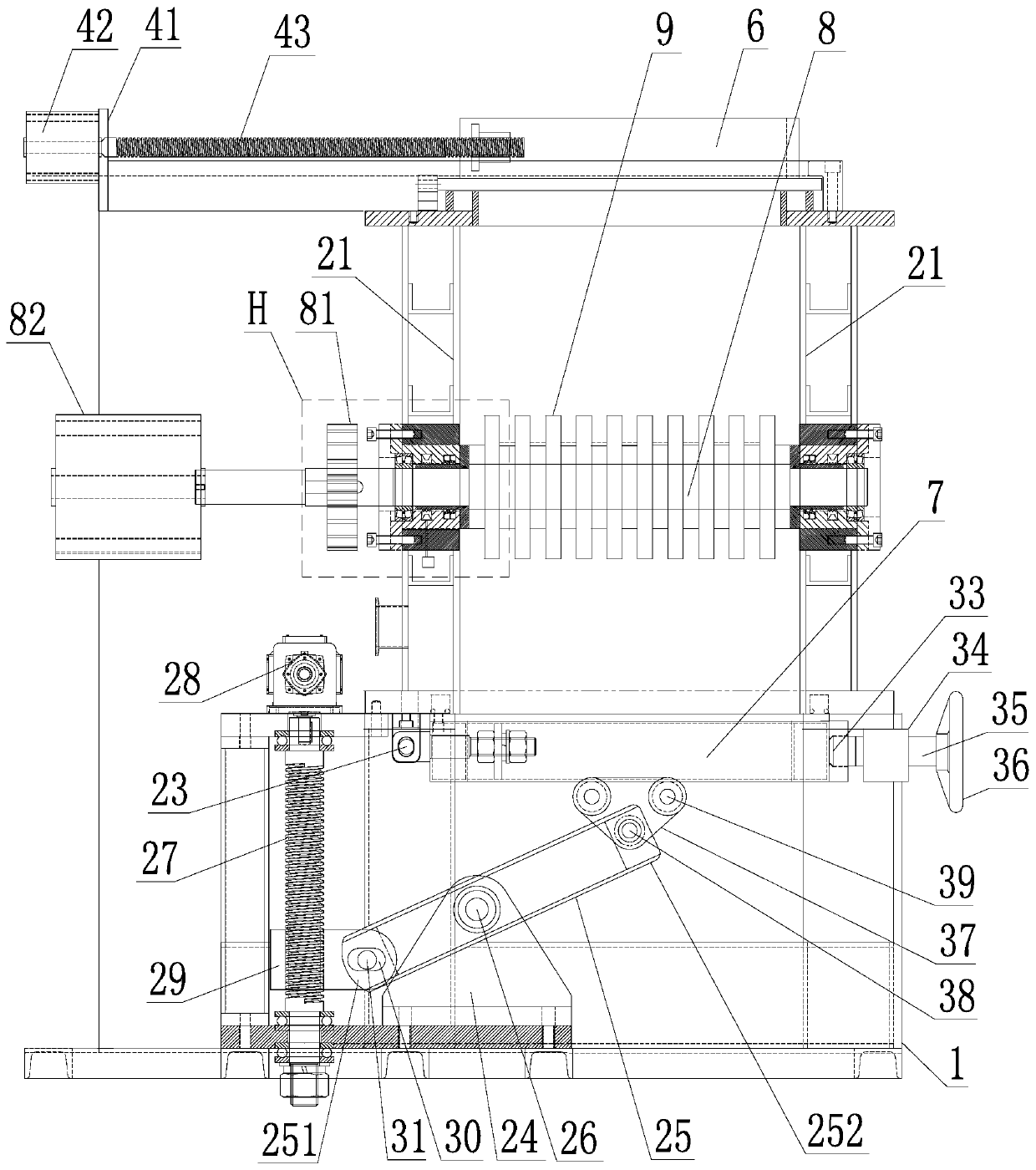
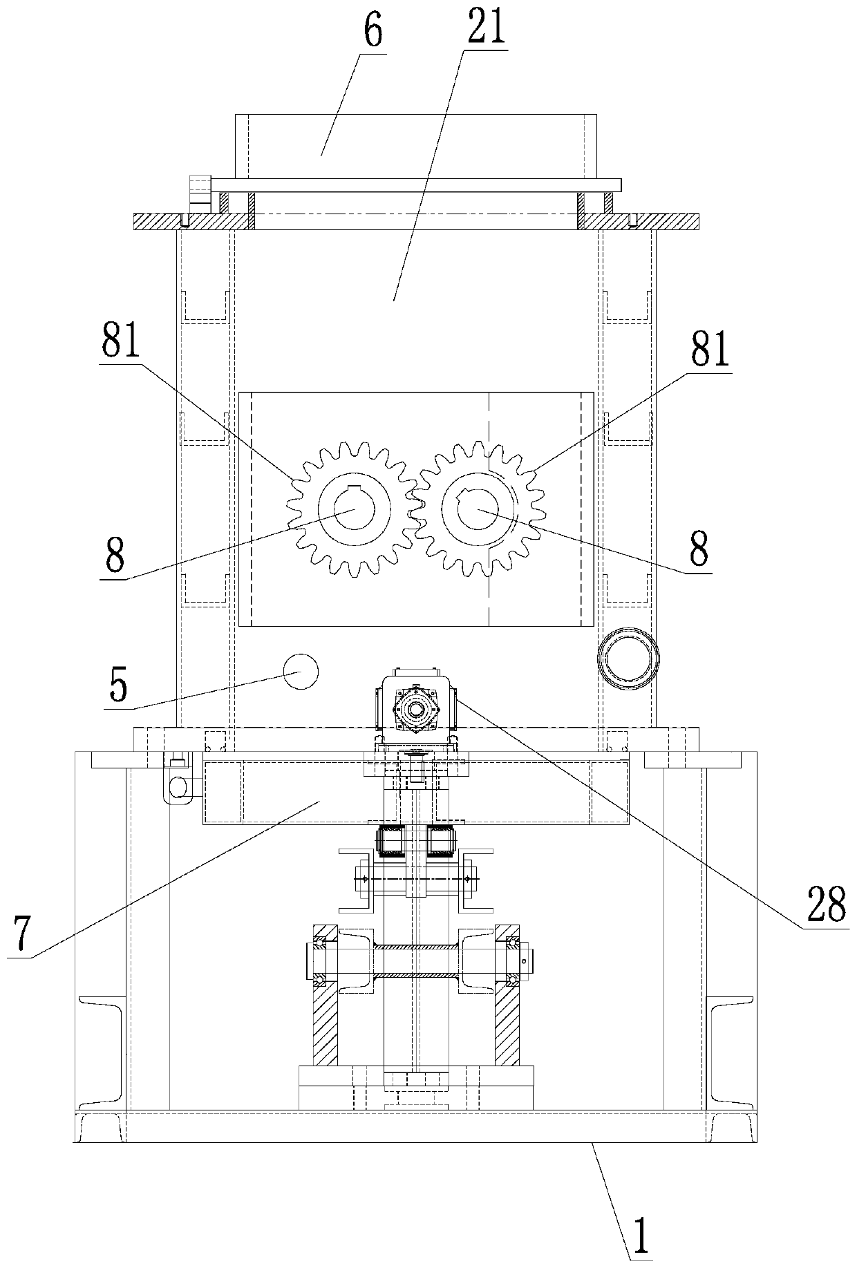
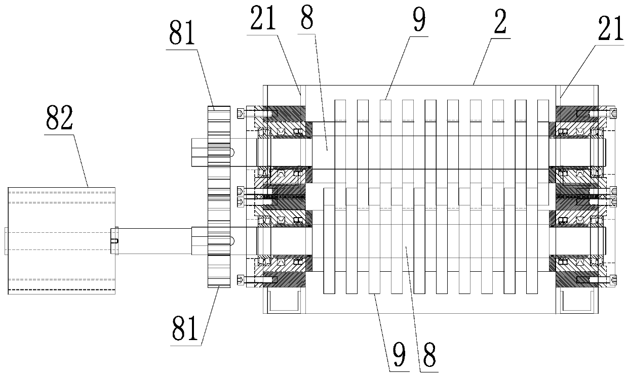
[0023] like figure 1 , figure 2 , image 3 , Figure 4 , Figure 5 As shown, the medical waste crushing and sterilization cabinet includes: a cabinet body 2 installed on a frame 1, a material inlet 3 is provided on the top of the cabinet body 2, and a material outlet 4 is provided at the bottom. The side plate 21 of the cabinet body 2 is provided with a steam inlet 5 connected with the steam source, and a top door 6 is provided at the feed port 3, and the top door 6 is driven by the top door drive assembly to open or close the feed port 3 of the cabinet body 2, A bottom door 7 is provided at the discharge port 4, and the bottom door 7 is driven by the bottom door drive assembly to open or close the discharge port 4 of the cabinet body 2. In the cabinet body 2, there are two parallel and movable supports on the cabinet body. For ...


PUM


Abstract

The invention discloses a medical waste crushing and sterilizing cabinet which comprises a cabinet mounted on a rack. A feed inlet is formed in the top of the cabinet and a discharge port is formed inthe bottom of the cabinet. A steam inlet communicating to a steam source is formed in a side plate of the cabinet. A top door is arranged at the feed inlet. The top door is driven by a top door driving assembly to open or close the feed inlet. A bottom door is arranged at the discharge port, and the discharge port is driven by a bottom door driving assembly to open or close the discharge port. Two spindles which are parallel to each other and are supported movably in the cabinet are arranged in the cabinet. The shaft end of each spindle is movably and hermetically mounted on the correspondingside plate through a shaft end sealing assembly. A plurality of slicers are separately mounted on each spindle axially, separately. Movable cutters between the two spindles are staggered to each other. The two spindles are driven by a spindle driving assembly and rotate downward oppositely at the same time, so that the movable cutters on the two spindles are matched with each other to crush medical waste. The medical waste crushing and sterilizing cabinet has the advantages that the medical waste crushing and sterilizing cabinet sterilizes and crushes the medical waste in the sterilizing cabinet, so that the sterilizing effect and the disposal efficiency are improved.

Description

technical field [0001] The invention relates to the technical field of medical waste crushing and sterilization equipment, in particular to a medical waste crushing and sterilization cabinet. Background technique [0002] Different from ordinary waste, medical waste is infectious, pathological, damaging, and chemical. If medical waste flows directly into the environment, it will easily cause air, water, and land pollution, which will easily affect people's physical and mental health. Therefore, it is necessary to Medical waste is sterilized. [0003] In the prior art, the treatment methods for medical waste mainly include incineration and non-incineration methods. Among them, the non-incineration methods mainly include the following methods: 1) steam sterilization; 2) pyrolysis treatment; 3) microwave treatment 4) plasma method. The steam sterilization method is relatively mature and can realize large-scale treatment, so it is widely used in the prior art. [0004] The wo...

Claims


Application Information

Patent Timeline
Patent Type & Authority Applications(China)
IPC IPC(8): B02C18/14B02C18/16A61L2/07A61L2/26
CPCB02C18/0084B02C18/14B02C18/16A61L2/07A61L2/26
Inventor 陈远华蒋忠伟刘朕火
Owner JIANGSU SHENNONG AUTOCLAVE
Why Eureka
Try Eureka