
Derusting device and method

A technology for mounting parts and boards, which is applied in the direction of grinding drive devices, grinding machines, and parts of grinding machine tools. It can solve problems such as low efficiency and high equipment failure rate, and achieve low efficiency, reduced personnel requirements, and simple forms. Effect

Active Publication Date: 2019-12-31
MCC BAOSTEEL TECH SERVICE
View PDF2 Cites 0 Cited by
  • Summary
  • Abstract
  • Description
  • Claims
  • Application Information

AI Technical Summary

Problems solved by technology

[0004] In view of the above shortcomings of the prior art, the purpose of the present invention is to provide a rust removal device and method for solving the technical problems of low efficiency and high equipment failure rate in the prior art

Method used


Image

  • Derusting device and method
  • Derusting device and method
  • Derusting device and method

Examples


Embodiment Construction

[0040] The implementation of the present invention will be illustrated by specific specific examples below, and those skilled in the art can easily understand other advantages and effects of the present invention from the contents disclosed in this specification.

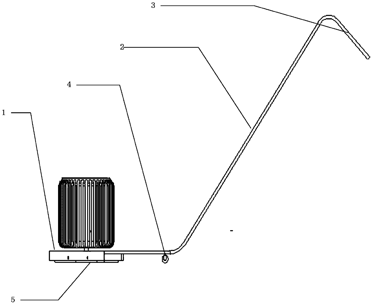
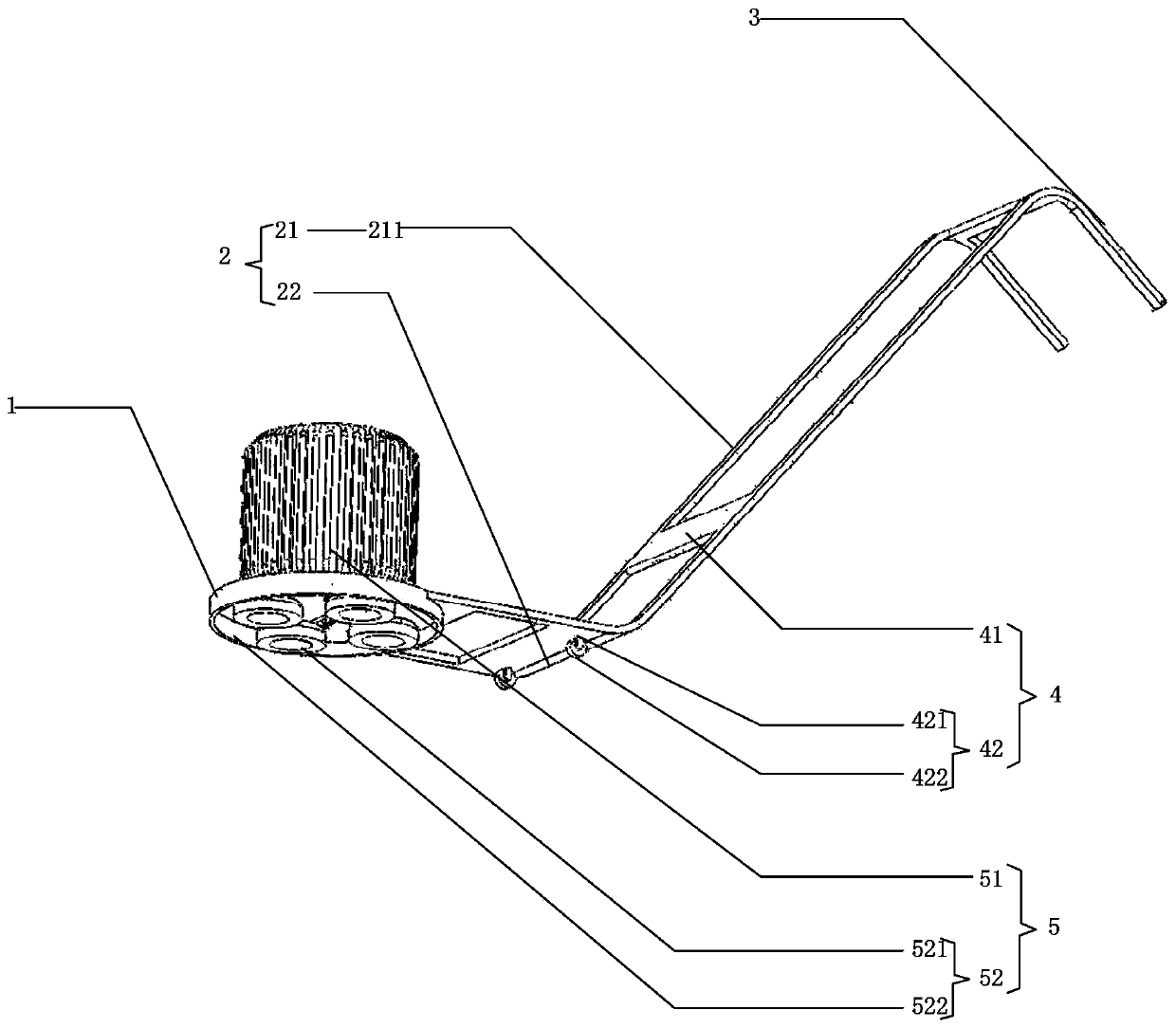
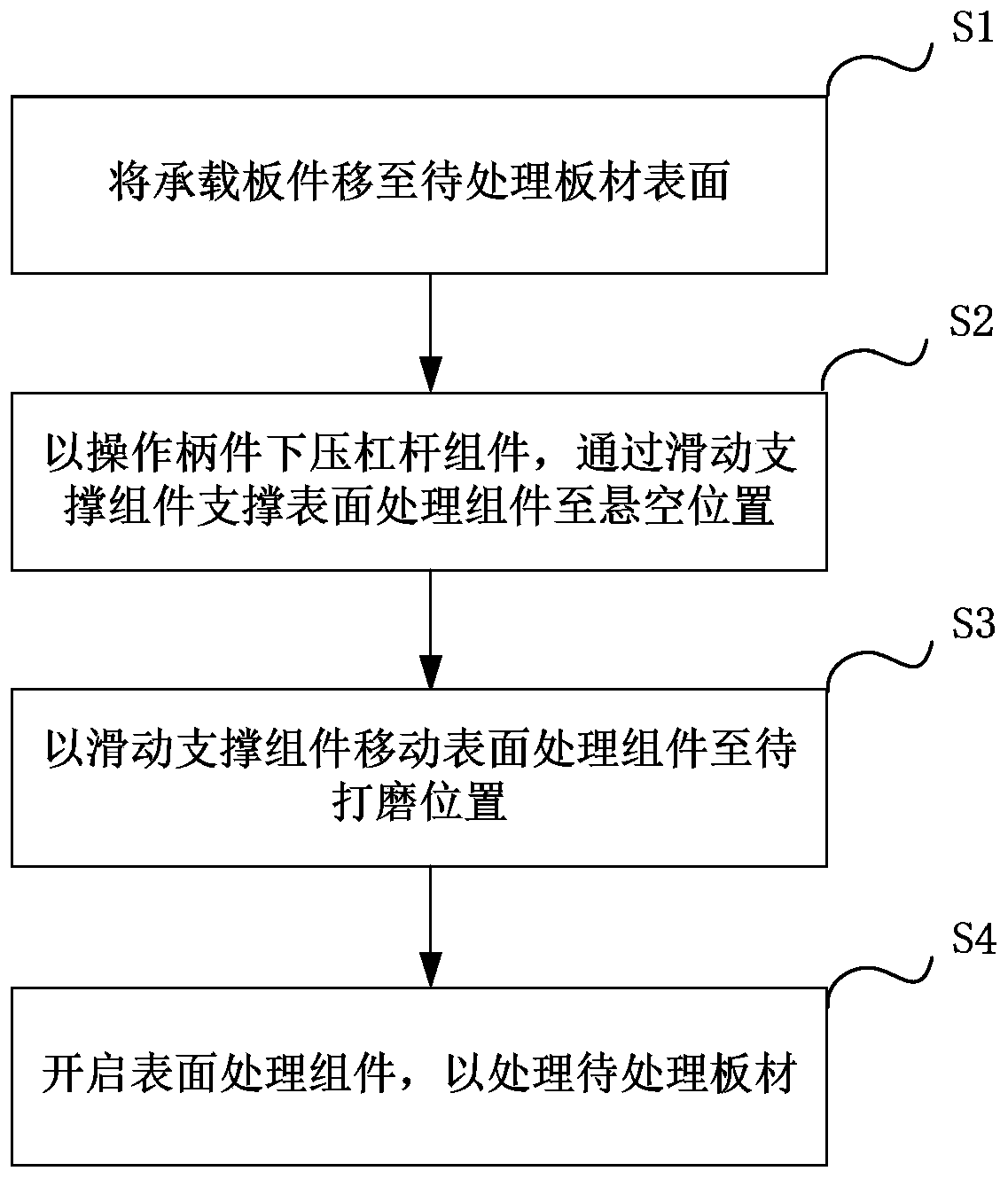
[0041] see Figure 1 to Figure 4 . It should be noted that the structures shown in the drawings attached to this specification are only used to match the content disclosed in the specification for the understanding and reading of those who are familiar with this technology, and are not used to limit the restrictive conditions for the implementation of the present invention, so there is no Technically, any modification of structure, change of proportional relationship or adjustment of size shall still fall within the scope of the technical content disclosed in the present invention without affecting the functions and objectives of the present invention. within the range that can be covered. At the same time, terms ...


PUM


Abstract

The invention provides a derusting device and method. The derusting device comprises a bearing plate member, a lever assembly, a holding frame, universal wheels and a derusting assembly, wherein the lever assembly forms on the bearing plate member in an extending mode; the holding frame forms on the end, away from the bearing plate member, of the lever assembly, the universal wheels are arranged at a joint position of the lever assembly and the bearing plate member, and the derusting assembly is fixedly arranged on the bearing plate member. The derusting device solves the problems of low efficiency and high equipment failure rate in the prior art.

Description

technical field [0001] The invention relates to a design technology of metallurgical production equipment, in particular to a derusting device and method. Background technique [0002] In recent years, metallurgical manufacturing and related equipment technology have developed rapidly. With the continuous replacement and optimization of the metallurgical industry in the metallurgical market environment, the design technology of metallurgical processes, metallurgical equipment and processing equipment has also been continuously updated. During the construction process, the metallurgical technology, process The requirements and requirements for the quality of metallurgical finished products have also increased. Among them, improving the efficiency and quality of the surface treatment of plates, such as grinding and rust removal, and the quality of the process is one of the problems that urgently need to be overcome. In the prior art, in order to ensure the quality of the produ...

Claims


Application Information

Patent Timeline
Patent Type & Authority Applications(China)
IPC IPC(8): B24B27/033B24B41/02B24B47/12
CPCB24B27/033B24B41/02B24B47/12
Inventor 贾胜利王兴思关辉王兴双刘友春
Owner MCC BAOSTEEL TECH SERVICE
Learn More