Scaffold rust removing device for bridge construction

A technology for bridge construction and scaffolding, which is used in grinding drive devices, manufacturing tools, metal processing equipment, etc., can solve the problems of high cost, low efficiency, large size and inconvenience.

Inactive Publication Date: 2018-02-09
程新锋
View PDF6 Cites 11 Cited by
  • Summary
  • Abstract
  • Description
  • Claims
  • Application Information

AI Technical Summary

Problems solved by technology

[0006] In order to overcome the shortcomings of the current derusting equipment, such as low efficiency, large volume, inconvenient movement, and high cost, the technical problem to be solved by the present invention is to provide a bridge construction equipment with high derusting efficiency, small volume and low cost. Scaffold derusting device

Method used


Image

  • Scaffold rust removing device for bridge construction
  • Scaffold rust removing device for bridge construction
  • Scaffold rust removing device for bridge construction

Examples


Embodiment 1

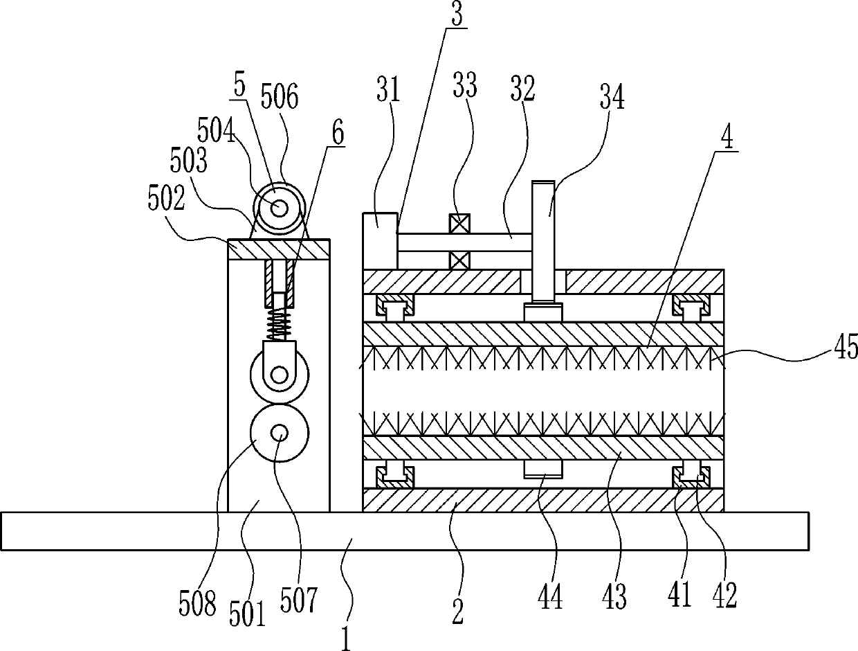
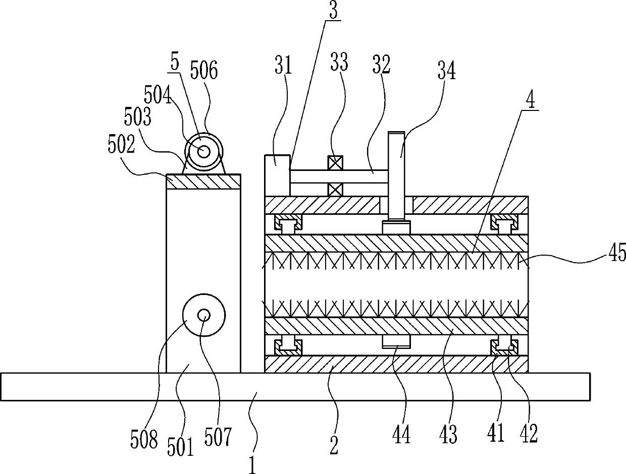
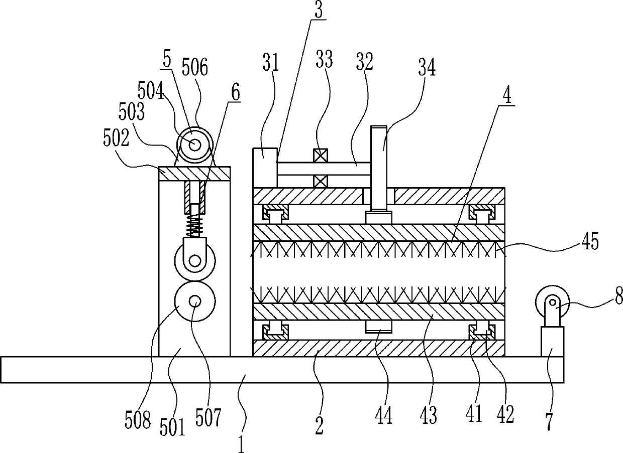
[0037] A scaffold derusting device for bridge construction, such as Figure 1-8 As shown, it includes a bottom plate 1, a box body 2, a driving device 3 and a derusting device 4. The middle of the top of the bottom plate 1 is connected with a box body 2 by means of bolt connection. The top of the box body 2 is provided with a driving device 3, and the box body 2 A derusting device 4 is provided inside.

Embodiment 2

[0039] A scaffold derusting device for bridge construction, such as Figure 1-8 As shown, it includes a bottom plate 1, a box body 2, a driving device 3 and a derusting device 4. The middle of the top of the bottom plate 1 is connected with a box body 2 by means of bolt connection. The top of the box body 2 is provided with a driving device 3, and the box body 2 A derusting device 4 is provided inside.

[0040] The driving device 3 includes a first motor 31, a first rotating shaft 32, a first bearing seat 33 and a gear 34, and the top left side of the box body 2 is respectively installed with the first motor 31 and the first bearing seat 33 by means of bolt connection, The first motor 31 is located on the left side of the first bearing seat 33, the output shaft of the first motor 31 is connected with the first rotating shaft 32 through a coupling, and the outside of the middle part of the first rotating shaft 32 interferes with the bearing in the first bearing seat 33 Connect...

Embodiment 3

[0042] A scaffold derusting device for bridge construction, such as Figure 1-8 As shown, it includes a bottom plate 1, a box body 2, a driving device 3 and a derusting device 4. The middle of the top of the bottom plate 1 is connected with a box body 2 by means of bolt connection. The top of the box body 2 is provided with a driving device 3, and the box body 2 A derusting device 4 is provided inside.

[0043] The driving device 3 includes a first motor 31, a first rotating shaft 32, a first bearing seat 33 and a gear 34, and the top left side of the box body 2 is respectively installed with the first motor 31 and the first bearing seat 33 by means of bolt connection, The first motor 31 is located on the left side of the first bearing seat 33, the output shaft of the first motor 31 is connected with the first rotating shaft 32 through a coupling, and the outside of the middle part of the first rotating shaft 32 interferes with the bearing in the first bearing seat 33 Connect...


PUM


Abstract

The invention relates to a rust removing device, in particular to a scaffold rust removing device for bridge construction. The scaffold rust removing device for bridge construction is high in rust removing efficiency, small in size and low in cost. In order to achieve the technical aims, the scaffold rust removing device for bridge construction comprises a base plate and the like. The middle partof the top of the base plate is connected with a box body in a bolted connection mode, and a driving device is arranged at the top of the box body. A rust removing device body is arranged inside the box body. According to the scaffold rust removing device for bridge construction, the driving device drives the rust removing device body to operate, the rust removing device body can remove iron ruston the scaffold surface, a pulling device is used for pulling a scaffold to move, and therefore efficiency is improved and the effects of being high in rust removing efficiency, small in size and lowin cost are achieved.

Description

technical field [0001] The invention relates to a derusting device, in particular to a scaffold derusting device for bridge construction. Background technique [0002] Bridges generally refer to structures erected on rivers, lakes and seas to allow vehicles and pedestrians to pass smoothly. In order to adapt to the modern high-speed development of the transportation industry, bridges are also extended to buildings that cross mountain streams, poor geology or meet other transportation needs to make traffic more convenient. A bridge is generally composed of a superstructure, a substructure, a support and ancillary structures. The superstructure is also called a bridge span structure, which is the main structure for crossing obstacles; the substructure includes abutments, piers and foundations; Or the force transmission device installed at the supporting place of the bridge abutment; the auxiliary structures refer to the bridge head board, conical slope protection, bank protec...

Claims


Application Information

Patent Timeline
Patent Type & Authority Applications(China)
IPC IPC(8): B24B27/033B24B47/12B24B41/00
CPCB24B27/033B24B41/005B24B47/12
Inventor 贺蔚敏张凯崔宏发其他发明人请求不公开姓名
Owner 程新锋
Why Eureka
Try Eureka