
Automatic sponge cutting machine for industrial processing

A sponge and automatic technology, applied in metal processing, etc., can solve the problems of waste of manpower and inconvenience, and achieve the effect of convenient transportation and maintaining unity and coordination

Inactive Publication Date: 2020-06-30
永康市大成工贸有限公司
View PDF5 Cites 0 Cited by
  • Summary
  • Abstract
  • Description
  • Claims
  • Application Information

AI Technical Summary

Problems solved by technology

[0002] Now with the development of society, the industry is increasingly pursuing automation and simplification. On the traditional sponge cutting machine, the cut sponges are generally stacked randomly. After cutting, it is very inconvenient and a waste of manpower to sort them out manually. Therefore, we It is necessary to set up an automatic sponge cutting bed for industrial processing, and design the structure of the sponge cutting bed so that the actions of the machine can maintain unity and coordination during the working process, and enable the machine to collect and stack the cut sponges without Manpower to organize, saving manpower, but also more convenient

Method used


Image

  • Automatic sponge cutting machine for industrial processing
  • Automatic sponge cutting machine for industrial processing
  • Automatic sponge cutting machine for industrial processing

Examples


Embodiment Construction

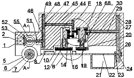
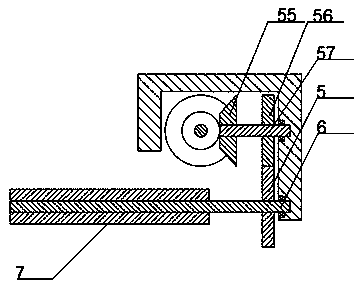
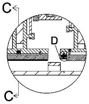
[0018] Combine below Figure 1-6 The present invention is described in detail, wherein, for the convenience of description, the orientations mentioned below are defined as follows: figure 1 The up, down, left, right, front and back directions of the projection relationship itself are the same.

[0019] combined with Figure 1-6 The automatic sponge cutting machine for industrial processing includes a body 1, the left side of the body 1 is provided with a running chamber 52, the inside of the running chamber 52 is provided with a first helical gear 53, and the left side wall of the running chamber 52 A first motor 2 is fixed inside, and the right end of the first motor 2 is power-fit connected with the first helical gear 53, and the rear side of the first helical gear 53 is meshed with a second helical gear 55, The center position of the second helical gear 55 is fixed with a first shaft 57 extending forward and backward. The rear side of the gear 55 is provided with a first ...


PUM


Abstract

The invention relates to the field of industrial processing and production, especially an automatic sponge cutting machine for industrial processing. The automatic sponge cutting machine for industrial processing includes a machine body. A running chamber is provided on the left side of the machine body, and a second A helical gear, the center of the first helical gear is provided with a first shaft, the left end of the first shaft is provided with a first motor, and the right side of the first motor is provided with a first rotating chamber, and the first rotating chamber The first bearing is arranged on the right side of the interior. The automatic sponge cutting machine for industrial processing provided by the present invention can realize automatic cutting of sponges, can freely adjust the width of sponge cutting, and can automatically collect the cut sponges after cutting the sponges. It is convenient for people to transport, and there is no need for manpower to stack the sponges. The linkage structure is used as much as possible in the structure, so that the movements of the machine can maintain unity and coordination during the working process.

Description

technical field [0001] The invention relates to the field of industrial processing and production, in particular to an automatic sponge cutting machine for industrial processing. Background technique [0002] Now with the development of society, the industry is increasingly pursuing automation and simplification. On the traditional sponge cutting machine, the cut sponges are generally stacked randomly. After cutting, it is very inconvenient and a waste of manpower to sort them out manually. Therefore, we It is necessary to set up an automatic sponge cutting bed for industrial processing, and design the structure of the sponge cutting bed so that the actions of the machine can maintain unity and coordination during the working process, and enable the machine to collect and stack the cut sponges without Manpower to organize, saving manpower, but also more convenient. Contents of the invention [0003] The object of the present invention is to provide an automatic sponge cut...

Claims


Application Information

Patent Timeline
Patent Type & Authority Patents(China)
IPC IPC(8): B26D11/00B26D1/06B26D7/12B26D7/32B26D5/22
CPCB26D1/06B26D5/22B26D7/12B26D7/32B26D11/00
Inventor 陈焻
Owner 永康市大成工贸有限公司
Learn More