Transmission channel and vehicle-mounted security inspection system including same

A transmission channel and channel technology, which is applied in the field of object or personnel transmission, can solve problems such as errors, conveyor belt deviation, etc., and achieve the effects of small friction, saving parts, and convenient position adjustment

Inactive Publication Date: 2019-12-31
ANHUI QILOOTECH PHOTOELECTRIC TECH
View PDF9 Cites 2 Cited by
  • Summary
  • Abstract
  • Description
  • Claims
  • Application Information

AI Technical Summary

Problems solved by technology

[0004] During the operation of the conveyor belt, the ideal state is that the line connecting the two center points of the driving roller and the driven roller is completely parallel to the running direction of the conveyor belt. However, during the installation process, there may be certain errors, which may cause the conveyor belt to run deviation in process

Method used


Image

  • Transmission channel and vehicle-mounted security inspection system including same
  • Transmission channel and vehicle-mounted security inspection system including same
  • Transmission channel and vehicle-mounted security inspection system including same

Examples


Embodiment 1

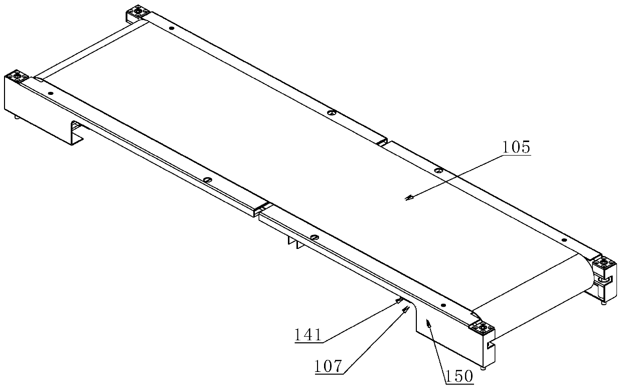
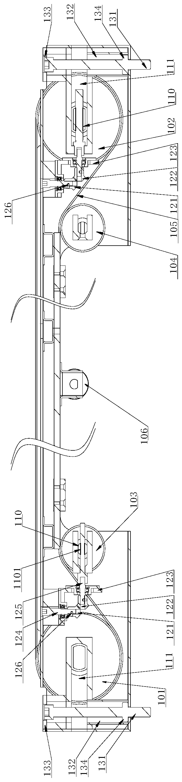
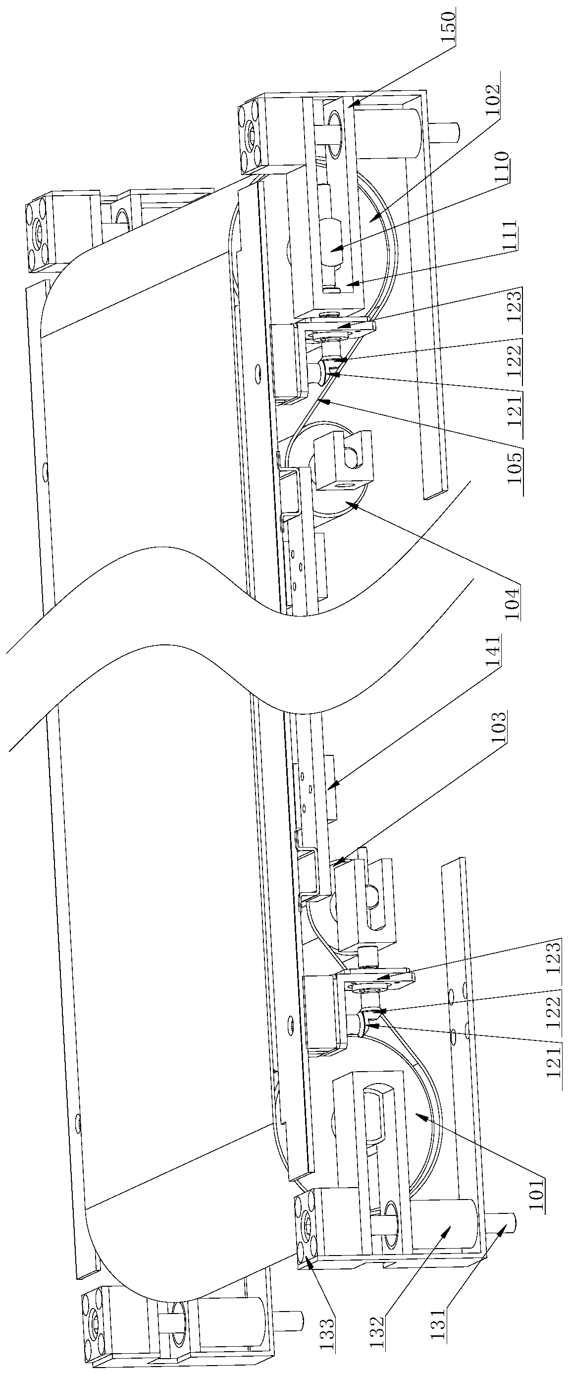
[0051] Such as Figure 1-4 As shown, a transmission channel 1 includes a closed loop conveyor belt 105, a driving roller 101 and a driven roller 102 passing through both ends of the conveyor belt 105 for supporting and driving the conveyor belt 105 to rotate, and a first guide roller 103 positioned below the conveyor belt 105 And the second guide roller 104, adjustment mechanism. The driven roller 102, the first guide roller 103 and the second guide roller 104 all include a support shaft 110, and the two ends of the support shaft 110 are arranged on the mounting frame 150, and the first guide roller 103 and the second guide roller The rollers 104 are respectively close to the driving roller 101 and the driven roller 102 ; and are located between the driving roller 101 and the driven roller 102 . The horizontal distance between the two ends of the first guide roller 103 and the driving roller 101 is adjustable, the horizontal distance between the two ends of the second guide r...

Embodiment 2

[0057] Such as Figure 5-8 As shown, the vehicle-mounted security inspection system including a transmission channel 1 described in Embodiment 1 also includes a radiation source assembly 200 and a detection assembly for human body detection. The transmission channel 1 described in Embodiment 1 is set on the radiation source assembly 200 Between the detector and the detection component, it is used to transmit the inspected person through the security check.

[0058] The radiation source assembly 200 includes a radiation source 2001 and a first support assembly for supporting the radiation source 2001. The radiation source 2001 is inclined and illuminates obliquely downward to the detector in the detection assembly. The radiation source 2001 illuminates the detection assembly obliquely downwards, so that the distance between the radiation source assembly 200 and the detection assembly will be reduced compared to the situation where the radiation source 2001 is facing directly, s...


PUM


Abstract

The invention relates to the field of object or person transmission, in particular to a transmission channel and a vehicle-mounted security inspection system including the same. The transmission channel includes a closed ring shape conveyor belt, an active roller which penetrates through both ends of the conveyor belt and is used for supporting and driving the conveyor belt to rotate, and a drivenroller, the channel further includes a first guide roller and a second guide roller which are located below the conveyor belt, the driven roller, the first guide roller, and the second guide roller each include a support shaft, both ends of the support shaft are arranged on a mounting frame, and the first guide roller and the second guide roller correspond to the driving roller and the driven roller respectively; the horizontal distance between the two ends of the first guide roller and the driving roller is adjustable, and the horizontal distance between the two ends of the second guide roller and the driven roller is adjustable. The transmission channel and the vehicle-mounted security inspection system including the same have the advantage that tension and deviation correction of the conveyor belt are realized by adjusting the positions of the two ends of the roller.

Description

technical field [0001] The invention relates to the field of object or personnel transmission, in particular to a transmission channel and a vehicle-mounted security inspection system including the channel. Background technique [0002] The transmission channel is used to transmit materials or human bodies, and can be used in many fields. Existing transmission channels include many ways, one of which is more commonly used is belt loop transmission. When conveying some lighter objects, it is only necessary to set a driving roller and a driven roller at both ends of the belt to drive the belt to rotate in a circular manner; The positions of the rollers and the driven rollers are all provided with guide rollers for support. [0003] Whether it is conveying light objects or heavy objects, looseness may occur during the conveying process. In order to facilitate installation, the size of the conveyor belt used will be larger than the ideal size, and the belt needs to be adjusted...

Claims


Application Information

Patent Timeline
Patent Type & Authority Applications(China)
IPC IPC(8): B65G15/00B65G23/04B65G23/44G01V5/00
CPCB65G15/00B65G23/04B65G23/44G01V5/00
Inventor 赵群礼张鹏冲夏国平李文军孙甲甲
Owner ANHUI QILOOTECH PHOTOELECTRIC TECH
Why Eureka
Try Eureka