Slewing mechanism, tooth side clearance adjustment method and crane

A technology of slewing mechanism and reducer, which is applied in the direction of cranes, mechanical equipment, belts/chains/gears, etc., can solve the problems of large adjustment unit span, poor adjustment accuracy, and small adjustment range, and achieve wide adjustment range, high precision, good continuity effect

Active Publication Date: 2021-10-26
XUZHOU HEAVY MASCH CO LTD
View PDF0 Cites 0 Cited by
  • Summary
  • Abstract
  • Description
  • Claims
  • Application Information

AI Technical Summary

Problems solved by technology

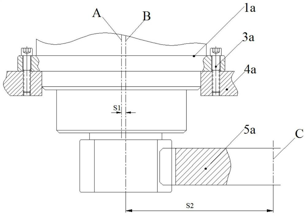
[0004] The existing rotary reducer 1a is connected to the rotary support 4a through 24 bolts. Therefore, when adjusting the backlash by rotating the rotary reducer 1a, there are only 12 positions to choose from. The adjustment unit has a large span and a small adjustment range. Make adjustment accuracy poor

Method used


Image

  • Slewing mechanism, tooth side clearance adjustment method and crane
  • Slewing mechanism, tooth side clearance adjustment method and crane
  • Slewing mechanism, tooth side clearance adjustment method and crane

Examples


Embodiment Construction

[0028] The following will clearly and completely describe the technical solutions in the embodiments of the present invention with reference to the accompanying drawings in the embodiments of the present invention. Obviously, the described embodiments are only some, not all, embodiments of the present invention. The following description of at least one exemplary embodiment is merely illustrative in nature and in no way taken as limiting the invention, its application or uses. Based on the embodiments of the present invention, all other embodiments obtained by persons of ordinary skill in the art without creative efforts fall within the protection scope of the present invention.

[0029] The relative arrangements of components and steps, numerical expressions and numerical values ​​set forth in these embodiments do not limit the scope of the present invention unless specifically stated otherwise. At the same time, it should be understood that, for the convenience of descriptio...


PUM


Abstract

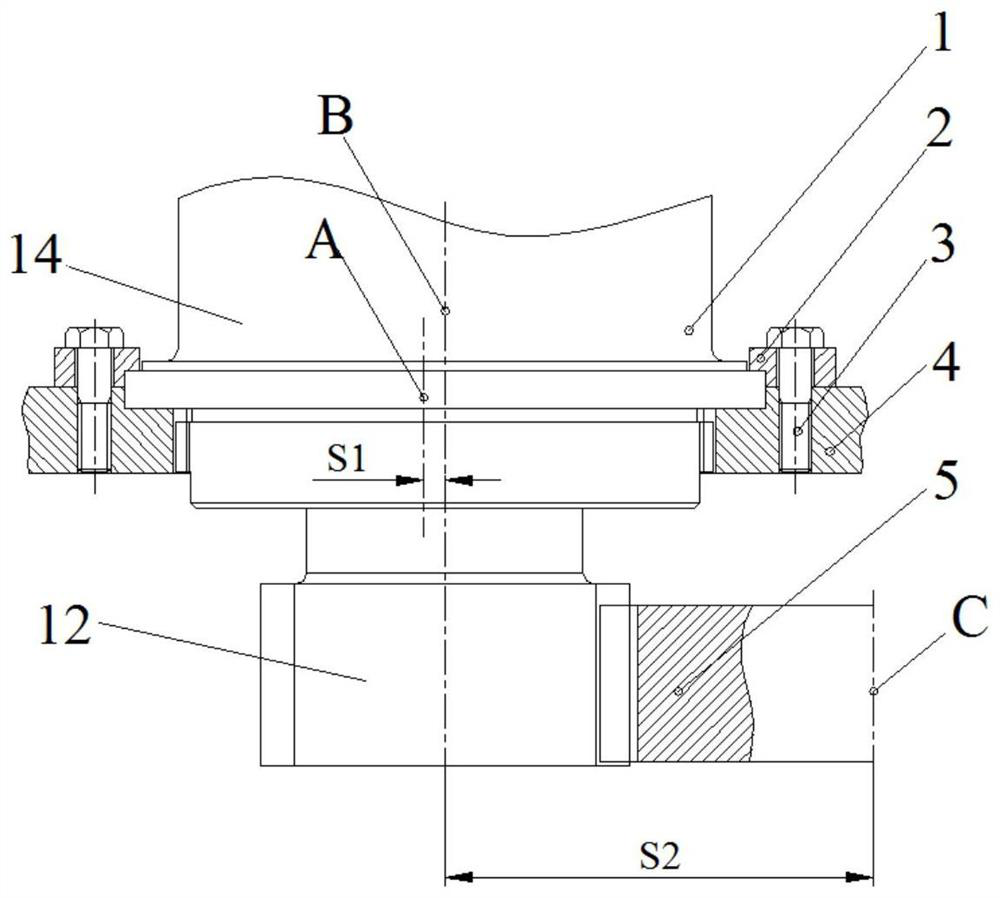
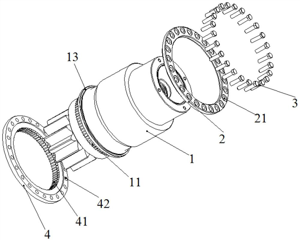
The invention discloses a slewing mechanism, a tooth side clearance adjustment method and a crane. The slewing mechanism includes a reducer, a slewing support and a slewing support; the slewing support has a mounting hole for sheathing and installing the reducer; the slewing support and the reducer housing are matched by splines, and the center lines of the splines are opposite It is arranged eccentrically on the center line of the transmission shaft of the reducer; and the slewing bearing is meshed with the gear of the output shaft of the reducer. The slewing mechanism of the present invention uses splines to connect the reducer and the slewing support. During the adjustment process of the tooth side clearance, the adjustment is performed in units of a single spline. Because the number of teeth of the splines is dense and evenly distributed, the tooth side clearance adjustment of the present invention Wider range, better continuity and higher precision.

Description

technical field [0001] The invention relates to the technical field of construction machinery, in particular to a slewing mechanism, a tooth side clearance adjustment method and a crane. Background technique [0002] Such as figure 1 As shown, the slewing mechanism in the prior art includes a slewing reducer 1a, a slewing support 4a, a slewing support 5a, a turntable support and a hydraulic device. The rotary reducer 1a is fixed on the rotary support 4a through the bolt group 3a, and the rotary support 5a is gear-engaged with the rotary reducer 1a. Wherein, the installation centerline A of the rotary reducer 1a is eccentrically set relative to the drive shaft centerline B of the rotary reducer 1a and the center distance between the above two centerlines is S1, the drive shaft centerline B of the rotary reducer 1a and The center distance between the centerlines C of the slewing bearings is S2. The hydraulic device provides power, and the slewing reducer 1a and slewing bear...

Claims


Application Information

Patent Timeline
Patent Type & Authority Patents(China)
IPC IPC(8): B66C23/84F16H57/12
CPCB66C23/84F16H57/12F16H2057/125
Inventor 张传世胡小冬任秀枝韩建营朱涛车少波
Owner XUZHOU HEAVY MASCH CO LTD
Why Eureka
Try Eureka