Stirring mechanism of reaction kettle

A stirring mechanism and reactor technology, applied in water/sludge/sewage treatment, biological water/sewage treatment, anaerobic digestion treatment, etc., can solve the problems of long fermentation process, dumping of organic matter to landfill, microbial pollution, etc. Achieve various forms and improve efficiency

Pending Publication Date: 2019-12-31
SHENZHEN YUZHI EQUIP TECH CO LTD
0 Cites 0 Cited by

AI-Extracted Technical Summary

Problems solved by technology

[0002]With the development of the catering industry, the treatment of kitchen waste has gradually become a difficult point in urban environmental governance. If it cannot be effectively treated, a large amount of organic matter will be dumped into landfill , pollute the environment, and simply feed livestock due to the large number of bacteria and other microorganisms, resulting in serious microbial pollution, such as swill pigs and other hygienic problems
In addition, harmful recycling methods such as kitchen waste oil are als...

Method used

Comprehensive above-mentioned: the agitating mechanism of a kind of reactor provided by the invention, by under the effect of horizontal agitator, longitudinal agitator and a plurality of side agitators, can stir the kitchen in the reactor from different directions Garbage, stirring in various forms, thus improving the efficiency of stirring. In addition, because the kitchen waste is fully stirred to make it fully decomposed, and after subsequent processing, no waste that pollutes the environment will be produced, thereby achieving the standard of zero pollution.
Concrete, horizontal stirring shaft 31 drives and rotates by horizontal driving motor 32, realizes the stirring of transverse direction, and longitudinal stirring shaft 21 drives and rotates by longitudinal driving motor 22, realizes the stirring of longitudinal direction, and lateral stirring shaft 41 passes through sideways The driving motor 42 drives the rotation to realize stirring in the lateral direction. Stirring in different directions makes the food waste in the reactor more evenly stirred, which is conducive to fermentation. In addition, a plurality of arc-shaped first stirring blades fixed on the outer surface of the transverse stirring shaft 31 are connected into a wave shape, constantly rotating and rolling to stir the kitchen waste in the reaction kettle to make it fully react.
In other embodiments, the outer surface of reactor body is provided with control box, is provided with microcontroller in control box, and microcontroller is electrically connected with stirring device, and according to the demand of stirring, microcontroller can control stirring device Work, thus improving the degree of intelligence, making the operation more convenient.
See also Fig. 2, the second stirring blade 211 and the 3rd stirring blade 411 all comprise axle sleeve 2111, and along the arc blade 2114 and linear blade that the center of axle s...

Abstract

The invention discloses a stirring mechanism of a reaction kettle. The stirring mechanism comprises a reaction kettle body and a stirring device; a feed inlet is disposed at the top of the reaction kettle body, and a discharge port is disposed at the bottom of the reaction kettle body; the stirring device comprises a transverse stirrer, a longitudinal stirrer and a plurality of lateral stirrers. Under the action of the transverse stirrer, the longitudinal stirrer and the plurality of lateral stirrers, the stirring mechanism of the reaction kettle provided by the invention can stir kitchen waste in the reaction kettle from different directions, and the stirring forms are various, so that the stirring efficiency is improved.

Application Domain

Treatment with anaerobic digestion processesBiological sludge treatment

Technology Topic

Engineering

Image

  • Stirring mechanism of reaction kettle
  • Stirring mechanism of reaction kettle

Examples

  • Experimental program(1)

Example Embodiment

[0018] In order to fully understand the technical content of the present invention, the technical solution of the present invention will be further introduced and illustrated below in conjunction with specific embodiments, but it is not limited thereto.
[0019] It should be understood that in this article, relational terms such as first and second are only used to distinguish one entity/operation/object from another entity/operation/object, and do not necessarily require or imply these entities/ There is any such actual relationship or sequence between operations/objects.
[0020] It should also be understood that the terms "include", "include" or any other variants thereof are intended to cover non-exclusive inclusion, so that a process, method, article or system including a series of elements not only includes those elements, but also includes The other elements listed may also include elements inherent to this process, method, article or system. If there are no more restrictions, the element defined by the sentence "including a..." does not exclude the existence of other identical elements in the process, method, article or system that includes the element.
[0021] See figure 1 , This embodiment provides a stirring mechanism for a reactor, including a reactor body 1 and a stirring device; the top of the reactor body 1 is provided with a feed port 11, and the bottom of the reactor body 1 is provided with a feed port 12; The stirring device includes a transverse stirrer 3, a longitudinal stirrer 2 and a plurality of lateral stirrers; the transverse stirrer 3 includes a transverse stirring shaft 31, and a transverse drive motor 32 fixed on the side wall of the reactor body 1, and a transverse stirring shaft 31 One end of the reactor body 1 is rotatably connected with one side arm of the reactor body 1, the other end of the horizontal stirring shaft 31 passes through the other side arm of the reactor body 1 and is connected to the output end of the horizontal drive motor 32, and the outer surface of the horizontal stirring shaft 31 is provided There are a plurality of first stirring blades 311 with a circular arc cross-sectional shape; the longitudinal stirrer 2 includes a longitudinal stirring shaft 21 and a longitudinal driving motor 22 fixed on the top of the reactor body 1, and the longitudinal stirring shaft 21 is located in the reactor body 1 , And located above the horizontal stirring shaft 31, the upper end of the vertical stirring shaft 21 passes through the top wall of the reactor body 1 and is connected to the output end of the longitudinal drive motor 22, and the longitudinal stirring shaft 21 is provided with a second outer surface close to its lower end. Stirring blade 211; The lateral agitator includes a lateral stirring shaft 41, and a lateral drive motor 42 fixed to the side arm of the reactor body 1, the outer end of the lateral stirring shaft 41 passes through the side wall of the reactor body 1 and The output end of the lateral drive motor 42 is connected, and the outer surface of the lateral stirring shaft 41 close to the inner end surface thereof is provided with a third stirring blade 411.
[0022] Specifically, the horizontal stirring shaft 31 is driven to rotate by the horizontal drive motor 32 to realize the stirring in the horizontal direction, the vertical stirring shaft 21 is driven to rotate by the longitudinal drive motor 22 to realize the stirring in the longitudinal direction, and the lateral stirring shaft 41 is driven by the lateral drive motor 42. Drive the rotation to achieve lateral stirring. Stirring in different directions makes the food waste in the reactor more evenly stirred, which is beneficial to fermentation. In addition, a plurality of arc-shaped first stirring blades fixed on the outer surface of the horizontal stirring shaft 31 are connected in a wave shape, and the food waste in the reactor is continuously rotated and tumbling to make it fully react.
[0023] In this embodiment, there are four lateral agitators, namely the first lateral agitator 4, the second lateral agitator 5, the third lateral agitator 6, and the fourth lateral agitator 7; the first side The side agitator 4 and the second side agitator 5 are on the same side, the third side agitator 6 and the fourth side agitator 7 are on the same side; the first side agitator 4, the second side agitator 5 They are arranged symmetrically with the third lateral agitator 6 and the fourth lateral agitator along the central axis of the reactor body 1 respectively. Among them, the first lateral stirrer 4 is located above the second lateral stirrer 5, and the third lateral stirrer 6 is located above the fourth lateral stirrer 7. Preferably, the first lateral agitator 4 is arranged inclined downward, and the second lateral agitator 5 is arranged inclined upward.
[0024] Optionally, the longitudinal agitator 2 further includes a fourth stirring blade 212 fixed to the lower end surface of the longitudinal stirring shaft 21. Preferably, the fourth stirring blade 212 is an anchor stirring blade. The anchor type stirring blade can further mix the food and kitchen in the reactor body 1 uniformly, and avoid the phenomenon of solid mass.
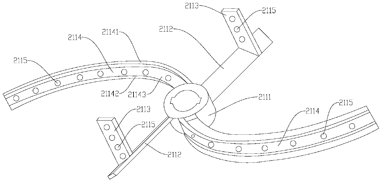
[0025] See figure 2 The second mixing blade 211 and the third mixing blade 411 both include a shaft sleeve 2111, and arc-shaped blades 2114 and linear blades arranged symmetrically along the center of the shaft sleeve 2111; the arc-shaped blades 2114 include an upper arc portion 21141 and a lower arc portion 21142 , And the middle arc face 21143 between the upper arc face 21141 and the lower arc face 21142, the width of the upper arc face 21141 is greater than the width of the middle arc face 21143, and the width of the lower arc face 21142 is the same as the width of the upper arc face 21141; The linear blade includes a first straight piece portion 2112 fixedly connected to the sleeve 2111, and a second straight piece portion 2113 fixed on the first straight piece portion 2112; the length direction of the first straight piece portion 2112 and the shaft of the sleeve 2111 The longitudinal direction of the second straight portion 2113 is parallel to the axial direction of the sleeve 2111. Specifically, by combining blades of different shapes, the mixing is more uniform and the mixing effect is better.
[0026] Preferably, a plurality of through holes 2115 are provided on both the arc-shaped blade 2114 and the linear blade at intervals. The through hole 2115 provided can not only reduce the resistance during stirring, but also make the stirring more uniform.
[0027] In other embodiments, the inner wall of the reactor body is provided with bumps, and preferably, the bump layer has a hemispherical shape. When the kitchen garbage flows and hits the bump, the hemispherical bump can give the garbage a reverse force in the 180° direction, so that the garbage is evenly dispersed. Furthermore, the inner wall where the bumps are located is connected with a high-pressure air source, and the air flows through the inner wall and the bumps to generate a strong air flow to agitate the fluid at the air head, which can not only produce a uniform stirring effect on the garbage, but also effectively prevent materials from adhering to On the inner wall of the reactor.
[0028] In other embodiments, the outer surface of the reactor body is provided with a control box. The control box is provided with a microcontroller. The microcontroller is electrically connected to the stirring device. According to the requirements of stirring, the microcontroller can control the operation of the stirring device. Improved the degree of intelligence, making the operation more convenient.
[0029] In summary: the invention provides a reaction kettle stirring mechanism, which can stir the food waste in the reaction kettle from different directions under the action of a horizontal stirrer, a longitudinal stirrer and a plurality of lateral stirrers. There are various forms to improve the efficiency of mixing. In addition, since the food waste is fully agitated to fully decompose it, and after subsequent processing, no waste material that pollutes the environment will be produced, thereby achieving the zero pollution standard.

PUM

no PUM

Description & Claims & Application Information

We can also present the details of the Description, Claims and Application information to help users get a comprehensive understanding of the technical details of the patent, such as background art, summary of invention, brief description of drawings, description of embodiments, and other original content. On the other hand, users can also determine the specific scope of protection of the technology through the list of claims; as well as understand the changes in the life cycle of the technology with the presentation of the patent timeline. Login to view more.

Similar technology patents

Terminal structure and micro encoder

PendingCN111934144Avarious forms
Owner:惠州市丰实卫奇电子科技有限公司

Red-leaf kochia scoparia shaping and landscaping method

PendingCN112075312Avarious forms
Owner:YANCHENG INST OF TECH

Photovoltaic tile assembly and preparation method thereof

PendingCN114695585Avarious formsSimple structure
Owner:苏州零碳绿建新能源科技有限公司

Electronic education system integrating images, texts, audios and videos

InactiveCN112767751AEnough informationvarious forms
Owner:李世军

Preparation method of alumina-based water-voltage generator functional area

InactiveCN112177835Avarious formsLess structured
Owner:YANCHENG TEACHERS UNIV

Classification and recommendation of technical efficacy words

  • various forms
  • Improve efficiency

Method and device for pushing information

ActiveCN106130871Avarious forms
Owner:TENCENT TECH (SHENZHEN) CO LTD

Combined type unmanned aerial vehicle

InactiveCN106081108AEasy to shootvarious forms
Owner:成都蜀尚星科技有限公司

Device for 3D printing of baking-free bricks through river and lake bottom mud and manufacturing method

PendingCN113510821Areduce transportationvarious forms
Owner:HOHAI UNIV +1

Valve plate for axial plunger motor

PendingCN112128049Areduce frictionvarious forms
Owner:龙工(上海)精工液压有限公司
Why Eureka
Try Eureka