
Inner valve spray hole reinforced sealing based magnetostrictive ultrasonic cleaning valve

A magnetostrictive and ultrasonic cleaning technology, which is applied in the direction of valve operation/release device, valve lift, valve details, etc., can solve the problems of accelerated water flow, waste of water source, and valves not tightly closed, etc.

Inactive Publication Date: 2019-12-31
谢曲坚
View PDF5 Cites 0 Cited by
  • Summary
  • Abstract
  • Description
  • Claims
  • Application Information

AI Technical Summary

Problems solved by technology

[0004] The main purpose of the present invention is to overcome the deficiencies of the prior art and provide a magnetostrictive ultrasonic cleaning valve based on the enhanced sealing of the inner valve nozzle to solve the problem of high-pressure water guns. With the acceleration of the speed, the high-pressure water is ejected from the main port or the left port and the right port with the help of ultrasonic waves. After the spraying is completed, the water flow is closed, that is to say, the inner valve is closed. Although the water flow is in a low pressure state, it still flows outward, which will push the inner shaft door, causing the valve to not be closed tightly, and part of the water flow continues to flow out, causing a waste of water.

Method used


Image

  • Inner valve spray hole reinforced sealing based magnetostrictive ultrasonic cleaning valve
  • Inner valve spray hole reinforced sealing based magnetostrictive ultrasonic cleaning valve
  • Inner valve spray hole reinforced sealing based magnetostrictive ultrasonic cleaning valve

Examples


Embodiment Construction

[0026] The following will clearly and completely describe the technical solutions in the embodiments of the present invention with reference to the accompanying drawings in the embodiments of the present invention. Obviously, the described embodiments are only some, not all, embodiments of the present invention. Based on the embodiments of the present invention, all other embodiments obtained by persons of ordinary skill in the art without making creative efforts belong to the protection scope of the present invention.

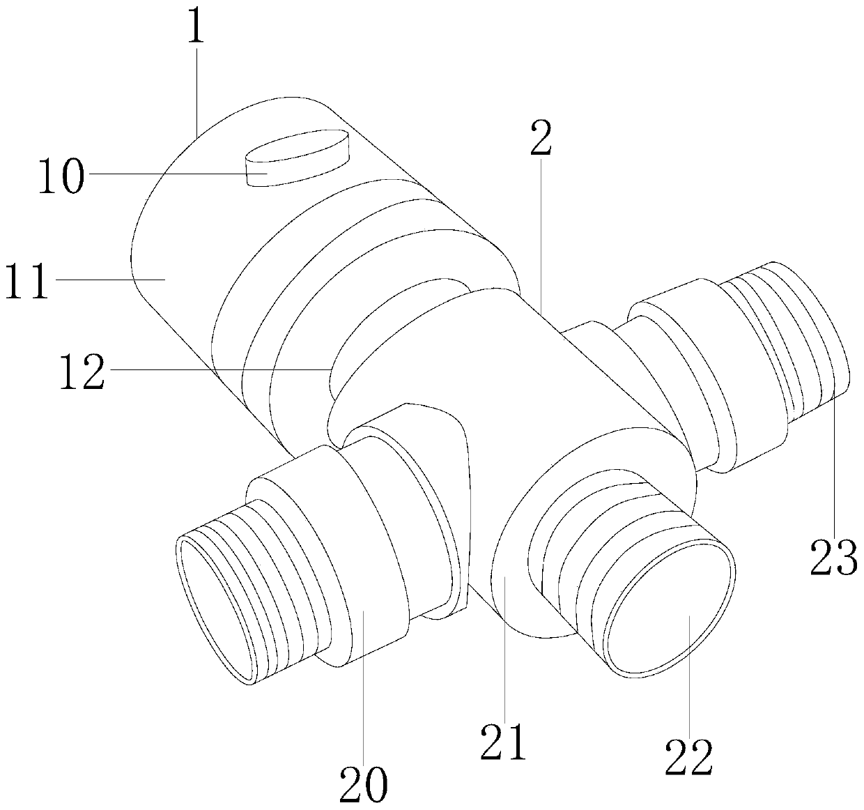
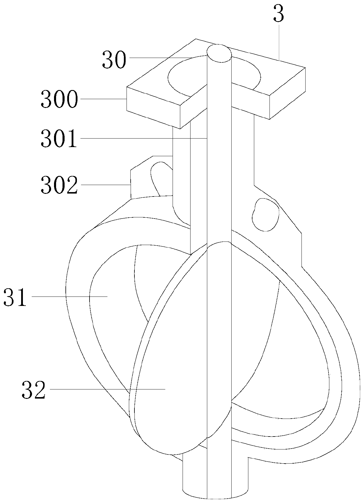
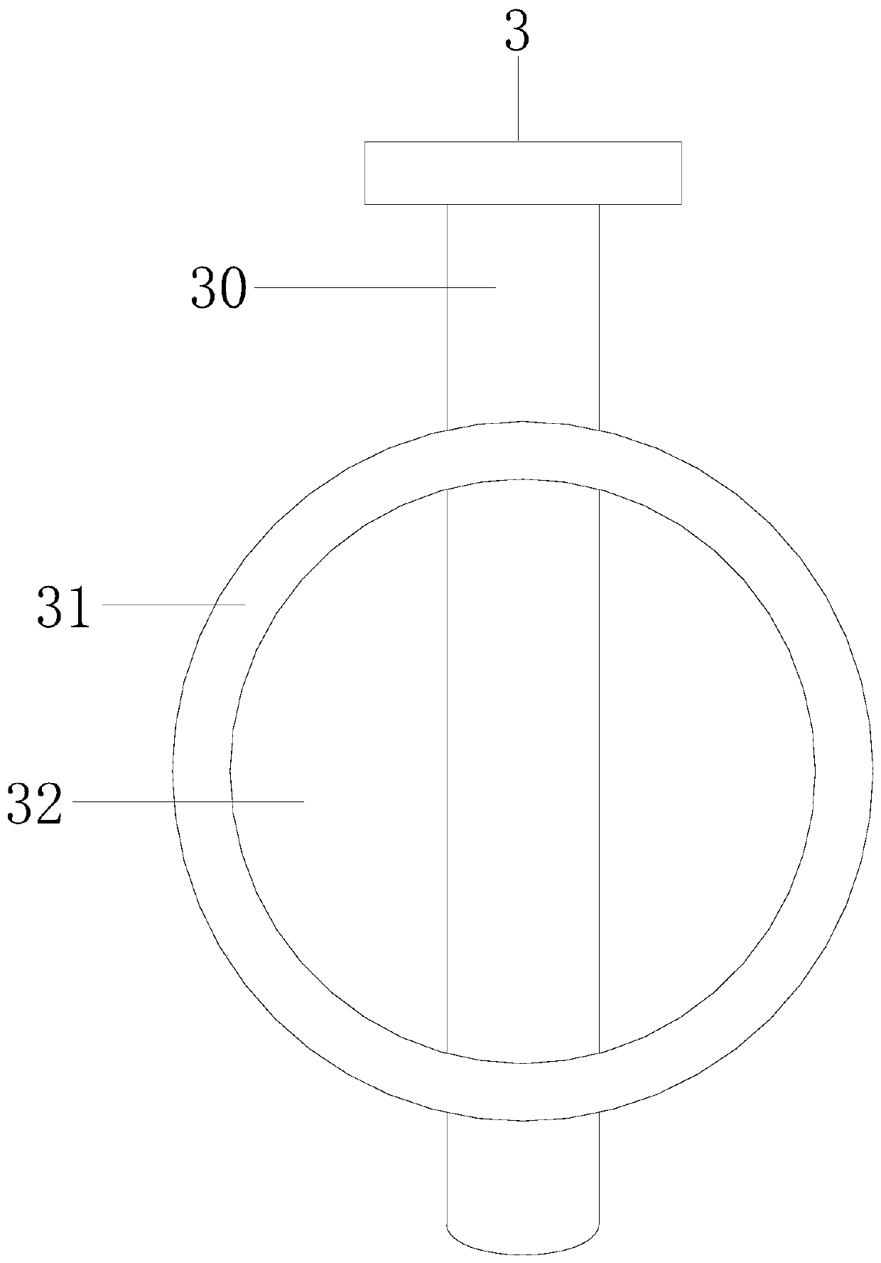
[0027] see Figure 1-8 , the present invention provides a magnetostrictive ultrasonic cleaning valve technical solution based on the enhanced sealing of the inner valve nozzle: its structure includes an installation valve structure 1, a split opening structure 2, and an inner valve structure 3, the installation valve structure 1 and the split opening structure 2 embedded, the inner valve structure 3 is installed on the branch structure 2 and communicated with ...


PUM


Abstract

The invention discloses an inner valve spray hole reinforced sealing based magnetostrictive ultrasonic cleaning valve. The inner valve spray hole reinforced sealing based magnetostrictive ultrasonic cleaning valve is characterized by structurally comprising a mounting valve structure, a split hole structure and an inner valve structure, wherein the mounting valve structure is embedded with the split hole structure; the inner valve structure is mounted on the split hole structure and communicates with the mounting valve structure; the mounting valve structure consists of a locking button, a valve barrel and a jointing tube, the locking button is mounted on the valve barrel, and the valve barrel is welded with the jointing tube; and the split hole structure comprises a left split hole, a split hole main barrel, a main split hole and a right split hole, and the split hole main barrel is in glue connection to the left split hole and the right split hole. In use, water flow is sprayed out from the main split hole or the left split hole and the right split hole by opening an inner shaft door; while the inner shaft door is closed, water flow is not sprayed, and the inner shaft door is driven by retraction of a telescopic magnetic pole to rotate to lock with an inner shaft ring to realize closing a valve hole; and after the valve hole is closed, the inner shaft ring and the inner shaftdoor separately transmit to realize reinforced fastening sealing of the inner valve hole.

Description

technical field [0001] The invention relates to the field of valves, in particular to a magnetostrictive ultrasonic cleaning valve based on enhanced sealing of inner valve nozzles. Background technique [0002] In recent years, ultrasonic cleaning has been widely used in the fields of dust removal, scale removal, and rust removal. Ultrasonic cleaning is conducted in liquids with fluctuations above the frequency of human hearing. When sound waves propagate in water, since sound waves are longitudinal waves, longitudinal waves push The action of the medium will cause the pressure change in the liquid to produce countless tiny vacuum bubbles. When the bubbles are burst under pressure, they will generate strong impact energy, which can break up the dirt fixed in the dead corner of the object and enhance the cleaning effect. Effect, in the cleaning process, the flow and closure of water are realized through the valve port in the water gun. [0003] The prior art high-pressure wa...

Claims


Application Information

Patent Timeline
Patent Type & Authority Applications(China)
IPC IPC(8): F16K1/22F16K1/228F16K1/32F16K27/02F16K31/06
CPCF16K1/221F16K1/224F16K1/2261F16K1/228F16K1/32F16K27/0218F16K31/0655
Inventor 谢曲坚
Owner 谢曲坚
Learn More