
A kind of ultra-thin heat pipe and its manufacturing process

An ultra-thin heat pipe and manufacturing process technology, applied in the field of heat pipes, can solve the problems of affecting the heat dissipation effect of the heat pipe, the length of the invalid end is large, and the space occupied is large, so as to shorten the processing cycle, improve the heat conduction efficiency, and reduce the overall weight.

Active Publication Date: 2021-03-16
SHANGHAI JIEYUAN ENVIRONMENTAL SCI & TECH
View PDF11 Cites 0 Cited by
  • Summary
  • Abstract
  • Description
  • Claims
  • Application Information

AI Technical Summary

Problems solved by technology

[0004] In order to solve the problem that the length of the invalid ends at both ends of the heat pipe is large, which affects the heat dissipation effect of the whole heat pipe, occupies a large space, and in the existing process, the heat pipe is bonded and then part of the bonded section is cut off, resulting in a cumbersome process. The present invention discloses a A kind of ultra-thin heat pipe and its manufacturing process,

Method used


Image

  • A kind of ultra-thin heat pipe and its manufacturing process
  • A kind of ultra-thin heat pipe and its manufacturing process
  • A kind of ultra-thin heat pipe and its manufacturing process

Examples


Embodiment 1

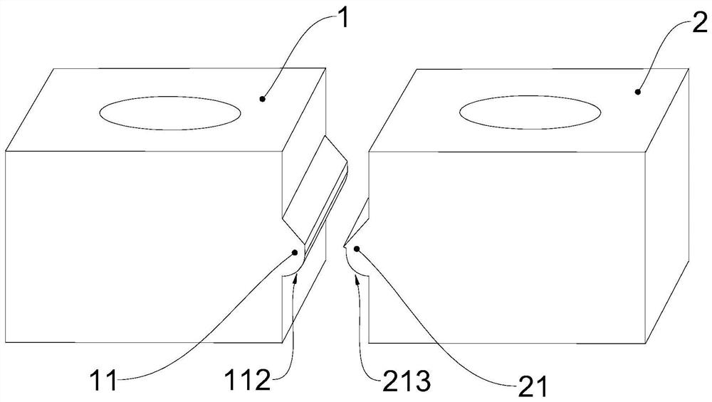
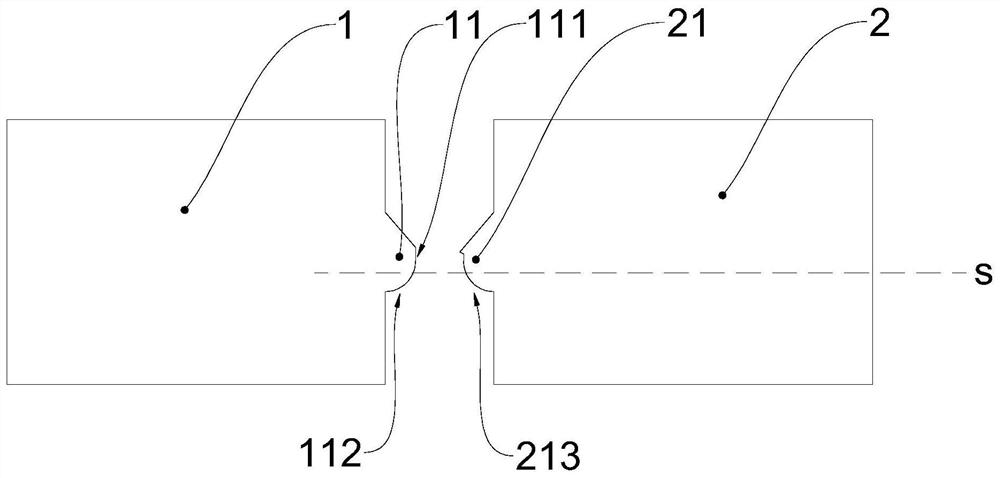
[0046] Such as Figure 2-4 As shown, the sealing and cutting mold includes a left mold 1 and a right mold 2, the side wall of the left mold 1 is provided with a sealing and cutting part 11, and the sealing and cutting part 11 has a sealing and cutting surface perpendicular to the horizontal plane s One 111, the side wall of the right mold 2 is provided with a sealing and cutting part two 21, the sealing and cutting part two 21 has a sealing and cutting surface two 211 and a cutter 212 perpendicular to the horizontal plane s, when sealing and cutting the heat pipe, The right mold 2 is close to the left mold 1, and the heat pipe is sealed by the pressing effect of the first sealing cutting surface 111 and the second sealing cutting surface 211, and the excess part is cut off by the cooperation between the cutter 212 and the first sealing cutting surface 111 .

Embodiment 2

[0048] Such as Figure 4 As shown, the vertical distance between the end of the sealing cutting surface 2 211 away from the cutter and the cutting edge of the cutter 212 is 1-5mm, so that the sealing width of the heat pipe (that is, the length of the dead end) is 1-5mm, and the heat pipe port is tightly sealed. At the same time, minimizing the length of the ineffective end is beneficial to improving the heat conduction efficiency of the heat pipe, reducing the volume of the heat pipe, saving the layout space of the heat pipe in the electronic product, and helping to reduce the overall weight of the electronic product.

Embodiment 3

[0050] Such as Figure 4 As shown, the cutter 212 is in contact with the top of the sealing cutting surface 211, and the bottom of the sealing cutting surface 1 111 and the bottom of the sealing cutting surface 2 211 are located on the same horizontal plane, which is conducive to neatly sealing the heat pipe.


PUM


Abstract

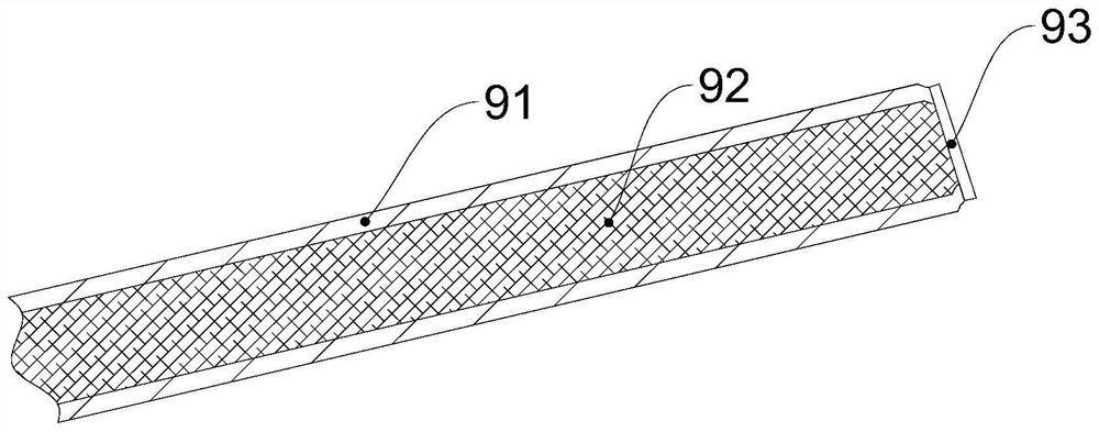
The invention belongs to the field of heat pipes and particularly relates to an ultrathin heat pipe and a manufacturing technology thereof. The ultrathin heat pipe comprises a flat copper pipe with two sealed ends, a capillary liquid absorbing core and a working medium. The capillary liquid absorbing core and the working medium are arranged in a copper pipe cavity. The wall thickness of the copperpipe is smaller than 0.3 mm. The total thickness of the copper pipe is smaller than 1 mm. The sealing width of the sealing ends of the ultrathin heat pipe is 1-5 mm. The sealing width of the ultrathin heat pipe reaches 1-5 mm, the sealing width is reduced greatly, the heat conducting efficiency of the heat pipe is improved beneficially, the size of the heat pipe is reduced, the arrangement spaceof the heat pipe in an electronic product is saved, the overall weight of the electronic product is reduced beneficially, and the yield is increased. A sealing and tailoring die can carry out tailoring work while the heat pipe is sealed, tight sealing of a pipe opening of the heat pipe and tailoring of the ineffective end are achieved through one step, pipe contracting does not need to be carriedout first, the manufacturing technology of the heat pipe is simplified greatly, and the machining period is shortened. After the copper pipe is flattened, liquid is injected, vacuumizing is carried out, the cavity space becomes small, the vacuum degree of the heat pipe is higher, and the heat efficiency of the heat pipe is improved.

Description

technical field [0001] The invention belongs to the field of heat pipes, and in particular relates to an ultra-thin heat pipe and a manufacturing process thereof. Background technique [0002] With the advancement of science and technology, today's electronic products are developing towards high function, high efficiency, and light and thin. Especially at present, 5G is the future development trend in the field of consumer electronics. Much higher than 4G chips, so the demand for heat dissipation in consumer electronics products will become stronger in the future. The increased power consumption of the chip has greatly increased the heat generated per unit area. How to quickly dissipate the heat of the chip has always been a difficulty and bottleneck in the industry. Therefore, superconducting thermal materials and heat dissipation materials that quickly conduct heat from chips need to be continuously improved and improved to solve the problem of chip heat dissipation in or...

Claims


Application Information

Patent Timeline
Patent Type & Authority Patents(China)
IPC IPC(8): F28D15/04
Inventor 罗合云周生国
Owner SHANGHAI JIEYUAN ENVIRONMENTAL SCI & TECH
Learn More