[0026] The present invention will be further described below in conjunction with accompanying drawing and specific embodiment:
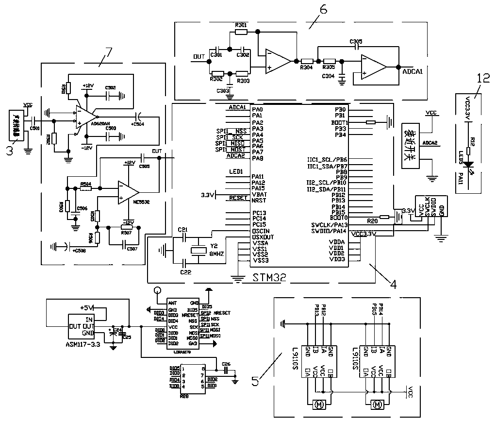
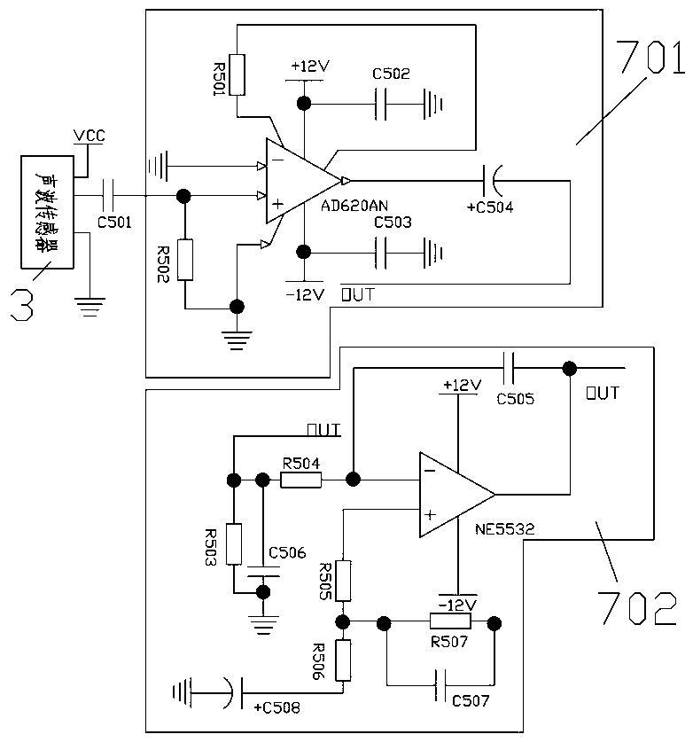
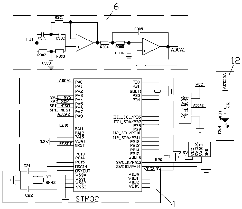
[0027] like Figure 1~6 As shown, a thermal insulation performance detection system for thermal insulation containers includes a detection device for conveying thermal insulation containers and detecting the thermal insulation structure of thermal insulation containers and a control system for judging the detection results, the detection The device includes a sounding device 1, a conveyor belt 2, a plurality of mechanical arms and an acoustic wave sensor 3 arranged on the mechanical arm. The acoustic wave sensor 3 is used to detect the sound waves emitted by the sounding device 1. The mechanical arm is equidistantly arranged along the outer arc of the conveyor belt 2, and the sounding device 1 is arranged at the intersection of the radiuses at both ends of the arc section of the conveyor belt 2;
[0028] Described control system is arranged on the mechanical arm, and control system comprises main control unit 4, sampling circuit and driving circuit 5, and described sampling circuit is used for sampling the detection signal of acoustic wave sensor 3, and the output terminal of described sampling circuit is connected Main control unit 4, the main control unit 4 is connected with a host computer, the main control unit 4 is used to control the action of the driving circuit 5 according to the output signal of the sampling circuit, and at the same time transmit the detection result to the host computer.
[0029] In order to ensure that the signal of the acoustic wave sensor 3 is not distorted during signal communication, so as to avoid detection errors, the sampling circuit includes a filter circuit 6, and the filter circuit 6 is used to perform noise reduction processing on the sampling signal, and the input terminal of the filter circuit 6 is connected to There is an amplifying circuit 7 , which includes a preamplifying circuit 701 and a secondary amplifying circuit 702 , and the input end of the amplifying circuit 7 is connected to the acoustic wave sensor 3 .
[0030] In order to ensure that the signal of the acoustic wave sensor 3 will not have errors such as drift or interference when transmitting, the preamplifier circuit 701 includes an operational amplifier chip, and the operational amplifier chip adopts an AD620AN type chip, and the same direction end of the operational amplifier chip Connect the output terminal of the acoustic wave sensor 3, the reverse terminal is grounded, the output terminal of the operational amplifier chip is connected to the secondary amplifier circuit 702, and the secondary amplifier circuit 702 includes an operational amplifier, and the operational amplifier adopts the NE5532 type chip, and the same direction of the chip The terminal is grounded, the reverse terminal is connected to the output terminal of the operational amplifier chip, and the output terminal is connected to the main control unit 4 .
[0031] In order to optimize the product structure, the main control unit 4 includes a minimum system of a single-chip microcomputer, and the single-chip microcomputer adopts a STC32 series single-chip microcomputer.
[0032] In order to make the detection device convenient for the main control unit 4 to control during the detection process, the drive circuit 5 is used to drive the mechanical arm and the conveyor belt 2 to work. The drive circuit 5 includes a drive chip, and the input terminal of the drive chip is connected to the IO of the single-chip microcomputer. The output end is connected to the manipulator and the conveyor belt 2 respectively. The drive chip adopts the L9110S type chip, and the input end of the drive chip is connected to the PB12~PB15 pins of the single-chip microcomputer, wherein the PB12 and PB13 of the single-chip microcomputer output the forward and reverse rotation of the mechanical arm motor Instructions, single-chip microcomputer PB14 and PB15 pins control the conveyor belt 2 motor to perform forward and reverse rotation.
[0033] In order to make the conveyor belt 2 in the coverage area of the sounding device, the motor of the conveyor belt 2 is stopped, and the upper end of one side of the inner arc surface of the conveyor belt 2 is provided with a proximity switch, and the proximity switch is connected to the PA8 pin of the single-chip microcomputer. The proximity switch is used to control Conveyor belt 2 starts and stops.
[0034] In order to optimize the product structure, the mechanical arm includes a base 8, a screw lifter 9, a motor and a fixed rod 10, the base 8 is a rectangular structure, the upper end surface of the base 8 is on the same plane as the conveyor belt 2, and the motor is fixed on the The upper end surface of the base 8, the output shaft of the motor is fixedly connected with the screw mandrel of the screw lifter 9, the worm screw of the screw screw lifter 9 is connected with the fixed rod 10, and the fixed rod 10 moves on the screw rod with the worm screw, and the fixed rod 10 It is a strip structure, the fixed rod 10 is arranged parallel to the screw rod, and the lower end of the fixed rod 10 is fixedly connected with the acoustic wave sensor 3 .
[0035] In order to reduce the interference that the screw lifter 9 produces to the acoustic wave sensor 3 when moving, a partition 11 is arranged between the lower end of the worm and the fixed rod 10, and the partition 11 is vertically arranged with the fixed rod 10, and the partition 11 The end face is fixedly connected with the worm.
[0036] In order to facilitate the staff to sort the insulated containers on the spot, an alarm mechanism is provided on the mechanical arm, and the alarm mechanism includes an LED lamp 12, which is connected to the PA11 pin of the single-chip microcomputer. The output signal is activated, and the LED lamp 12 is used to display the detection result of the current container on site.
[0037] like figure 1 As shown, in this embodiment, in order to facilitate the communication between the main control unit 4 and the host computer, the wireless communication module is arranged between the control unit 4 and the host computer, and the wireless communication module includes a wireless transceiver chip, and the wireless transceiver The chip adopts LORA1278 chip, and the NSS, SCK, MOSI and MISO pins of the wireless transceiver chip are respectively connected to the PA4~PA7 pins of the microcontroller.
[0038] like Image 6 As shown, in this embodiment, in order to facilitate batch testing, baffles are equidistantly arranged on the conveyor belt 2, and the conveyor belt 2 is divided into several equal parts with equal areas, and the staff places the heat preservation container between the two baffles, In order to improve work efficiency, when the conveyor belt 2 on one side is inspected, the conveyor belt 2 on the other side is placed in the thermal container.
[0039] In this embodiment, the sound generating device 1 adopts an intelligent sound wave generator produced by Fukeda Precision Machinery Changxing Co., Ltd., the screw lifter 9 adopts an electric screw lifter produced by Hangzhou Linkong Machinery Co., Ltd., and the acoustic wave sensor 3 Adopt the high-precision acoustic wave sensor produced by Japan Keyence Keyence.
[0040] When detecting the heat preservation structure of the heat preservation container, first turn on the generator 1, the frequency of the sound generator 1 can be adjusted, the generator 1 emits a sound wave of a certain frequency, and the sound wave sensor 3 detects the sound wave and transmits the sound wave signal to the main control unit 4 , the single-chip microcomputer of the main control unit 4 sends different control instructions to the detection device respectively according to the frequency range of the acoustic wave signal. Y1. X0~X1 is the frequency range of the sound wave received by the acoustic wave sensor 3 when it is outside the heat preservation container. X1~Y1 is the frequency range of the sound wave received by the sound wave sensor 3 when it enters the heat preservation container. When the receiving frequency is not between X0~Y1, the heat preservation container is kept warm There are problems in the structure, and the thermal insulation performance of the thermal insulation container does not meet the standard.
[0041] When the frequency of the sound wave signal received by the main control unit 4 is between X0 and X1, the PB13 pin of the microcontroller sends a high-level signal to the drive circuit 5, and the drive chip controls the motor of the mechanical arm to reverse, the fixed rod 10 descends, and the sound wave sensor 3 Entering the interior of the heat preservation container, the motor of the mechanical arm stops, and the detection starts. The acoustic wave sensor 3 receives the sound wave signal from the generator 1 inside the heat preservation container. Main control unit 4, the single-chip microcomputer records the current sound wave detection frequency, compares the sound wave detection frequency with the frequency range of X1~Y1 written by itself, and finally sends the comparison result and sound wave detection frequency to the host computer, and the host computer For data storage, when the sound wave frequency is not between X0~Y1, the PA11 pin of the single-chip microcomputer is at a high level, and the LED light 12 is turned on to light up, reminding the field staff that the current thermal insulation performance of the thermal insulation container is unqualified.
[0042] After 15 seconds, the PB13 pin of the single-chip microcomputer sends a high-level signal, the motor of the mechanical arm rotates forward, the screw lifter 9 drives the fixed rod 10 to rise, and the acoustic wave sensor 3 protrudes from the inside of the heat preservation container at the same time. At this time, a detection cycle ends. After the PB13 pin of the single-chip microcomputer is at a high level for 5 seconds, the PB14 pin of the single-chip microcomputer moves, and the motor of the conveyor belt 2 rotates. When the proximity switch of the conveyor belt 2 on the other side reaches the detection position, the rotation of the motor of the conveyor belt 2 stops, and another batch of heat preservation containers Enter the backup.
[0043] The embodiments described above are only preferred embodiments of the present invention, and do not limit the implementation scope of the present invention, so all equivalent changes or modifications made according to the structure, features and principles described in the patent scope of the present invention should be Included in the patent scope of the present invention.