Monitoring system based on gas valve control

A monitoring system and gas valve technology, applied in valve operation/release device, valve details, valve device, etc., can solve problems such as endangering people, forgetting to turn off the fire, and gas accidents cannot be effectively prevented, so as to reduce the expansion of accidents. , the effect of reducing the occurrence of secondary accidents

Pending Publication Date: 2019-12-31
深圳前海中科胜铭科技有限公司
View PDF0 Cites 2 Cited by
  • Summary
  • Abstract
  • Description
  • Claims
  • Application Information

AI Technical Summary

Problems solved by technology

However, people may forget to turn off the gas equipment after using the gas equipment, or the gas equipment itself fails, resulting in gas leakage. Once the gas leakage occurs in a closed and airtight environment, it will directly endanger people's lives. and property safety
[0003] Although some residents are equipped with gas alarms in their homes, the gas alarms will send out an alarm when they detect a gas leak in the room. However, when no one is at home, the gas alarms cannot inform users or The gas company and even the fire department, so no one can close the gas valve in time to prevent further gas leakage, and gas accidents cannot be effectively prevented
And some users often forget to turn off the fire or worry about whether the fire at home has been turned off when they go out.

Method used


Image

  • Monitoring system based on gas valve control
  • Monitoring system based on gas valve control
  • Monitoring system based on gas valve control

Examples


Embodiment Construction

[0027] In order to facilitate the understanding of the present invention, the present invention will be described more fully below with reference to the associated drawings. Preferred embodiments of the invention are shown in the accompanying drawings. However, the present invention can be embodied in many different forms and is not limited to the embodiments described herein. On the contrary, the purpose of providing these embodiments is to make the disclosure of the present invention more thorough and comprehensive.

[0028] It should be noted that when an element is referred to as being “fixed” to another element, it can be directly on the other element or there can also be an intervening element. When an element is referred to as being "connected to" another element, it can be directly connected to the other element or intervening elements may also be present. The terms "vertical," "horizontal," "left," "right," and similar expressions are used herein for purposes of ill...


PUM


Abstract

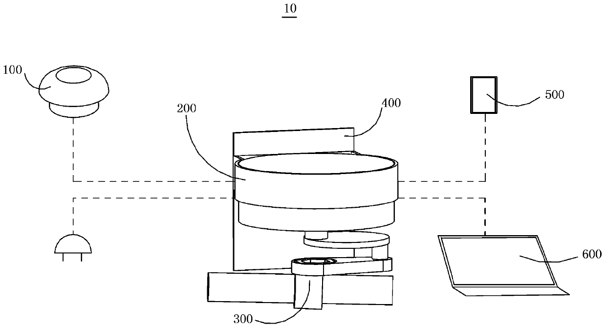
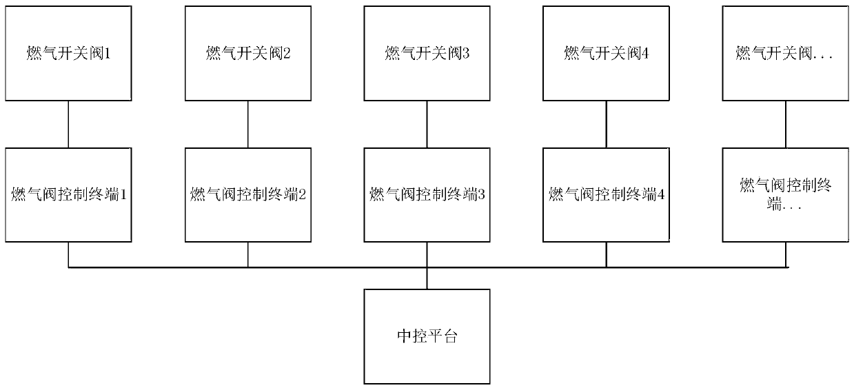
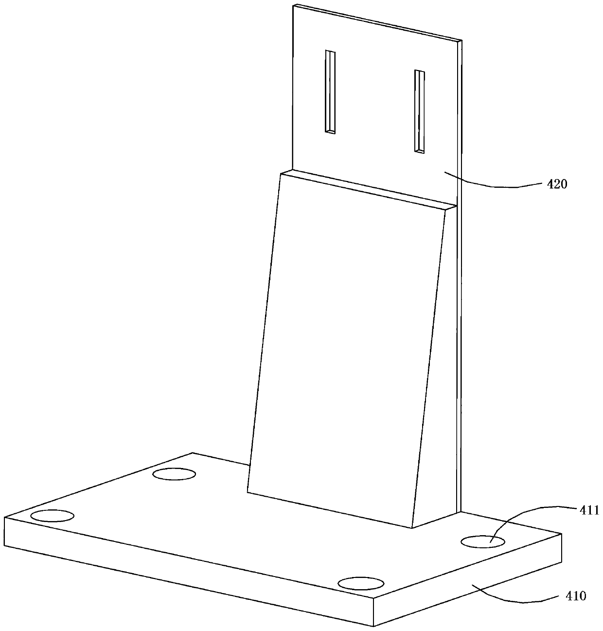
The application discloses a monitoring system based on gas valve control, comprising a comprehensive sensor, gas valve control terminals, gas switching valves, a control terminal placing rack, a mobile terminal and a center control platform, wherein the comprehensive sensor is used for sensing the temperature, the concentration of gas and carbon monoxide, and feeding sensing values back to the gasvalve control terminals, the gas valve control terminals are used for opening or closing the gas switching valves, the control terminal placing rack is used for fixing the gas valve control terminalson the gas switching valves, the mobile terminal is used for displaying the sensing values of the comprehensive sensor, and is capable of remotely controlling the gas valve control terminals to openor close the gas switching valves, the center control platform is used for monitoring the plurality of gas switching valves. The monitoring system of the invention is capable of monitoring indoor gasconditions of users in real time and remotely controlling open or close of gas valves, so as to play a certain role in preventing dangerous cases, through adoption of the monitoring system, relevant departments can achieve monitoring for gas conditions of multiple users, thus the monitoring system is worthy of promotion and application.

Description

technical field [0001] The present application relates to the field of gas valve control and monitoring, in particular to a monitoring system based on gas valve control. Background technique [0002] In people's daily life, gas appliances such as gas stoves have been requisite equipment for people. However, people may forget to turn off the gas equipment after using the gas equipment, or the gas equipment itself fails, resulting in gas leakage. Once the gas leakage occurs in a closed and airtight environment, it will directly endanger people's lives. and property safety. [0003] Although some residents are equipped with gas alarms in their homes, the gas alarms will send out an alarm when they detect a gas leak in the room. However, when no one is at home, the gas alarms cannot inform users or The gas company and even the fire department, so no one can close the gas valve in time to prevent further gas leakage, and there is no way to effectively prevent gas accidents. An...

Claims


Application Information

Patent Timeline
Patent Type & Authority Applications(China)
IPC IPC(8): G08B21/16G01D21/02F16K31/04
CPCF16K31/046G01D21/02G08B21/16
Inventor 臧学亮李江波
Owner 深圳前海中科胜铭科技有限公司
Why Eureka
Try Eureka