
A low power consumption control method and control circuit of a permanent magnet synchronous motor

A technology of permanent magnet synchronous motor and control method, which is applied in the direction of motor generator control, electronic commutation motor control, electromechanical brake control, etc., and can solve the problem of insufficient calculation accuracy of integrator power tube flux linkage and insufficient steady-state loss control effect Good, the hysteresis width is difficult to determine and other problems, to avoid the calculation algorithm and hardware detection circuit, high reliability, reduce useless loss effect

Active Publication Date: 2021-08-24
BEIJING MECHANICAL EQUIP INST
View PDF0 Cites 0 Cited by
  • Summary
  • Abstract
  • Description
  • Claims
  • Application Information

AI Technical Summary

Problems solved by technology

With the development of power electronics technology and motor control theory, high-performance permanent magnet synchronous motor closed-loop control methods represented by vector control and direct torque control have been rapidly developed and widely used. The advantages of vector control and direct torque control are both The dynamic performance of the motor is good, but the disadvantage is that the steady-state loss control effect for long-term operation is not good enough, and on the basis of the good dynamic performance brought by direct torque control, the defect that the switching frequency is not fixed is introduced, resulting in a large problem loss
[0003] In recent years, the method of motor power control has been developed, which reduces the problematic power of the motor to a certain extent, but the disadvantage is that the switching frequency is not fixed, and the hysteresis width is difficult to determine
At the same time, in order to complete power control, it is necessary to calculate the size and angle of flux linkage in real time, but in the case of low-frequency operation, changes in motor stator parameters, error accumulation of integrators, switching dead zones of power tubes and temperature drift problems lead to flux linkage problems. The calculation accuracy is not high enough, which affects the loss of the motor

Method used


Image

  • A low power consumption control method and control circuit of a permanent magnet synchronous motor
  • A low power consumption control method and control circuit of a permanent magnet synchronous motor
  • A low power consumption control method and control circuit of a permanent magnet synchronous motor

Examples


Embodiment 1

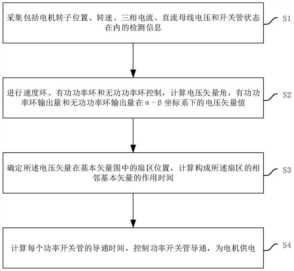
[0042] This embodiment provides a low power consumption control method for a permanent magnet synchronous motor, such as figure 1 shown, including the following steps:

[0043] Step S1, collecting detection information including motor rotor position, rotational speed, three-phase current, DC bus voltage and power switch tube state;

[0044] Step S2, performing speed loop, active power loop and reactive power loop control on the motor according to the detection information;

[0045]Through speed loop, active power loop and reactive power loop control, calculate the voltage vector angle, active power loop output and reactive power loop output; and obtain the active power loop output and reactive power loop output through coordinate transformation The voltage vector of the quantity in the α-β coordinate system;

[0046] Specifically, step S2 includes the following sub-steps:

[0047] Step S2-1, calculating the active power feedback value p and the reactive power feedback value...

Embodiment 2

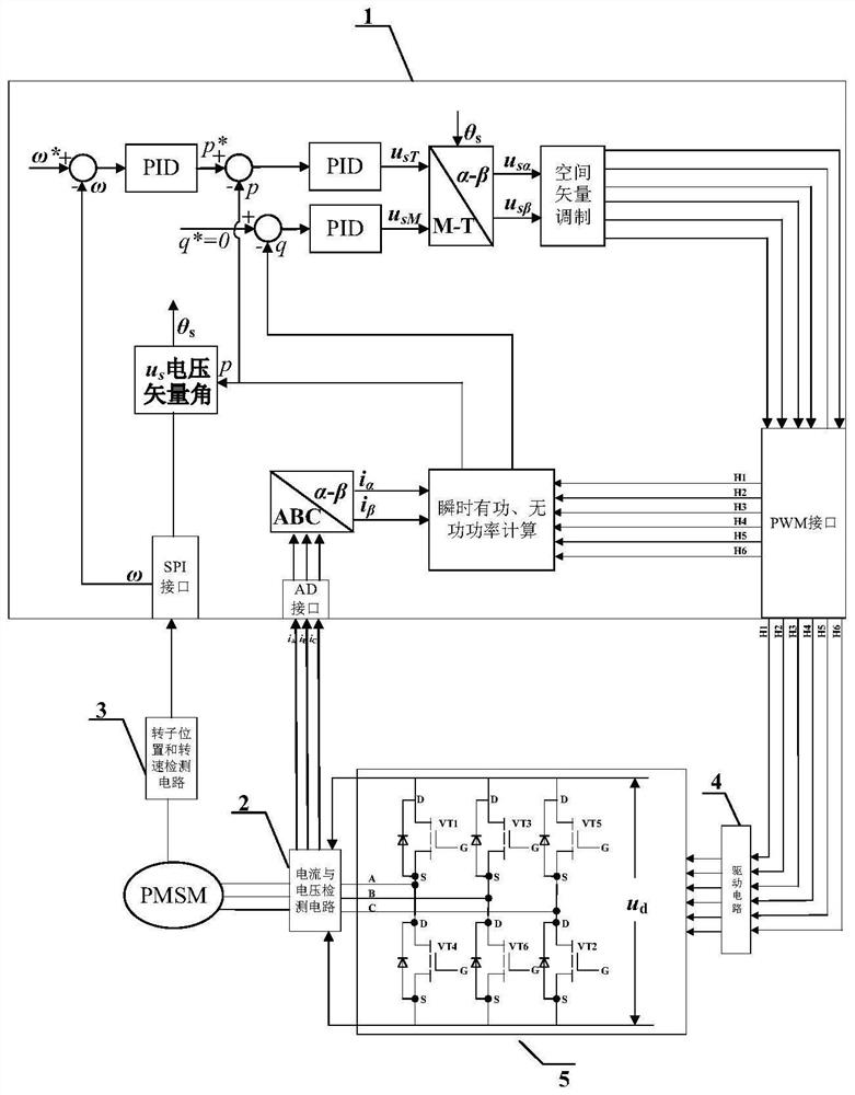
[0087] This embodiment provides a low power consumption control circuit for a permanent magnet synchronous motor, such as image 3As shown, it includes a DSP controller (1), a current and voltage detection circuit (2), a rotor position and rotational speed detection circuit (3), a drive circuit (4), and a power main circuit (5).

[0088] The current and voltage detection circuit (2) is used to collect three-phase current information and DC bus voltage information, and send them to the DSP controller (1);

[0089] Specifically, the described three current sensors including current and voltage detection circuit (2) and its conditioning circuit, a voltage acquisition circuit and its conditioning circuit, through the AD interface of the DSP controller (1) will collect three-phase current information and direct current The bus voltage information is sent to the DSP controller.

[0090] The rotor position and rotational speed detection circuit (3) is used to collect the rotational ...


PUM


Abstract

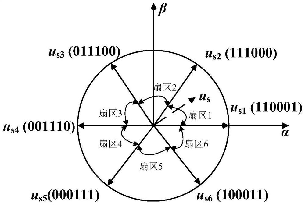
The application discloses a low power consumption control method and control circuit of a permanent magnet synchronous motor, which belongs to the technical field of motor control and solves the problem of low loss of a permanent magnet synchronous motor; the method includes collecting detection information of the motor; loop, active power loop and reactive power loop control; carry out space vector modulation, determine the sector position of the voltage vector in the basic vector diagram, and calculate the action time of the adjacent basic vectors constituting the sector; according to the sector The position and the action time of the adjacent basic vectors of the sector calculate the turn-on time of each power switch tube, and control the power switch tube to turn on to supply power to the motor. The invention improves the problem of high loss in the long-term operation of the permanent magnet synchronous motor, and has simple realization and high reliability.

Description

technical field [0001] The invention relates to the technical field of motor control, in particular to a low power consumption control method and a control circuit of a permanent magnet synchronous motor. Background technique [0002] Permanent magnet synchronous motors have the advantages of high power density, small rotor moment of inertia, small armature inductance, high operating efficiency, and no slip rings and brushes on the rotating shaft. They are widely used in the field of high-performance motion control in the small and medium power range. With the development of power electronics technology and motor control theory, high-performance permanent magnet synchronous motor closed-loop control methods represented by vector control and direct torque control have been rapidly developed and widely used. The advantages of vector control and direct torque control are both The dynamic performance of the motor is good, but the disadvantage is that the steady-state loss contro...

Claims


Application Information

Patent Timeline
Patent Type & Authority Patents(China)
IPC IPC(8): H02P21/08H02P21/00
CPCH02P21/0003H02P21/08
Inventor 崔臣君李浩李俊峰李方俊周通韩士玉
Owner BEIJING MECHANICAL EQUIP INST
Learn More