Permanent magnet synchronous motor low-power-consumption control method and control circuit
A technology of permanent magnet synchronous motor and control method, which is applied in the direction of motor generator control, electronic commutation motor control, electromechanical brake control, etc., and can solve the problem of insufficient calculation accuracy of integrator power tube flux linkage and insufficient steady-state loss control effect Good, hysteresis width is difficult to determine and other problems, to avoid hardware detection circuit, high reliability, reduce useless loss effect
- Summary
- Abstract
- Description
- Claims
- Application Information
AI Technical Summary
Problems solved by technology
Method used
Image
Examples
Embodiment 1
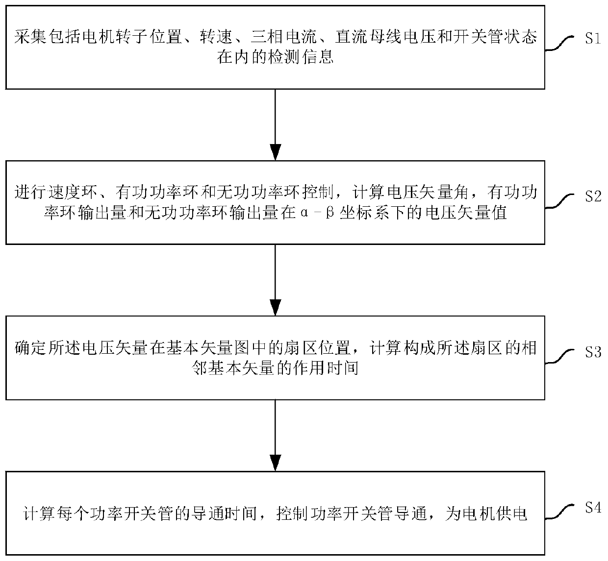
[0042] This embodiment provides a low power consumption control method for a permanent magnet synchronous motor, such as figure 1 shown, including the following steps:
[0043] Step S1, collecting detection information including motor rotor position, rotational speed, three-phase current, DC bus voltage and power switch tube state;
[0044] Step S2, performing speed loop, active power loop and reactive power loop control on the motor according to the detection information;
[0045]Through speed loop, active power loop and reactive power loop control, calculate the voltage vector angle, active power loop output and reactive power loop output; and obtain the active power loop output and reactive power loop output through coordinate transformation The voltage vector of the quantity in the α-β coordinate system;
[0046] Specifically, step S2 includes the following sub-steps:
[0047] Step S2-1, calculating the active power feedback value p and the reactive power feedback value...
Embodiment 2
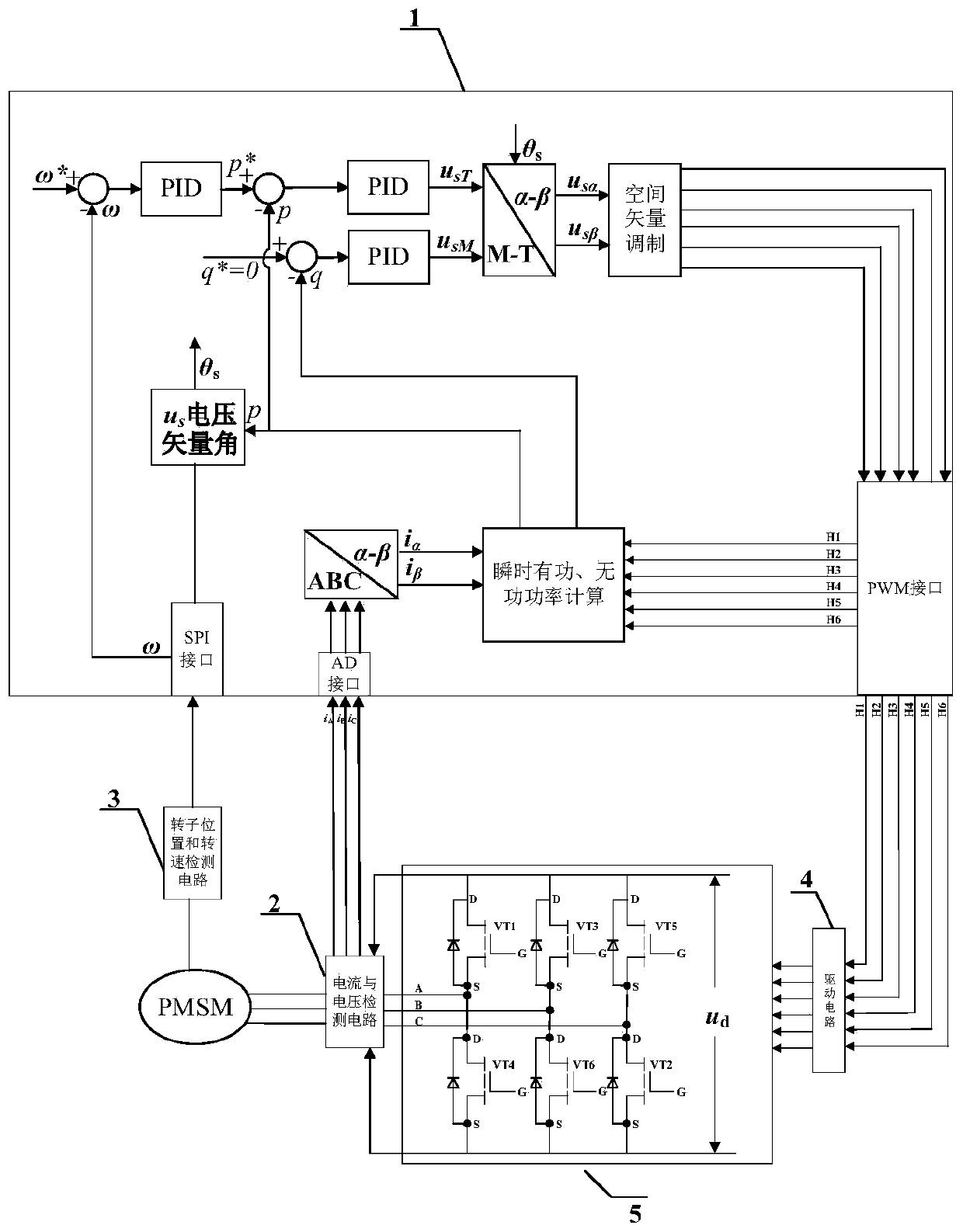
[0087] This embodiment provides a low power consumption control circuit for a permanent magnet synchronous motor, such as image 3As shown, it includes a DSP controller (1), a current and voltage detection circuit (2), a rotor position and rotational speed detection circuit (3), a drive circuit (4), and a power main circuit (5).
[0088] The current and voltage detection circuit (2) is used to collect three-phase current information and DC bus voltage information, and send them to the DSP controller (1);
[0089] Specifically, the described three current sensors including current and voltage detection circuit (2) and its conditioning circuit, a voltage acquisition circuit and its conditioning circuit, through the AD interface of the DSP controller (1) will collect three-phase current information and direct current The bus voltage information is sent to the DSP controller.
[0090] The rotor position and rotational speed detection circuit (3) is used to collect the rotational ...
PUM
 Abstract
Description
Claims
Application Information
 - R&D
- Intellectual Property
- Life Sciences
- Materials
- Tech Scout
- Unparalleled Data Quality
- Higher Quality Content
- 60% Fewer Hallucinations
Browse by: Latest US Patents, China's latest patents, Technical Efficacy Thesaurus, Application Domain, Technology Topic, Popular Technical Reports.
© 2025 PatSnap. All rights reserved.Legal|Privacy policy|Modern Slavery Act Transparency Statement|Sitemap|About US| Contact US: help@patsnap.com


