Automatic accompanying bed

A companion bed, automatic technology, applied in the field of furniture, can solve the problems of easily disturbing the patient, bumping, and exerting a lot of force, and achieves the effect of good thermal insulation, improved utilization, and avoidance of overflow loss.

Pending Publication Date: 2020-01-03
THE FIRST AFFILIATED HOSPITAL OF ARMY MEDICAL UNIV
View PDF9 Cites 0 Cited by
  • Summary
  • Abstract
  • Description
  • Claims
  • Application Information

AI Technical Summary

Problems solved by technology

[0004] However, the current companion bed is completely dependent on manual deployment, and manual deployment cannot fully and accurately grasp the strength of the deployment, resulting in excessive force, the companion bed unfolds rapidly, and the legs of the companion bed coll

Method used


Image

  • Automatic accompanying bed
  • Automatic accompanying bed
  • Automatic accompanying bed

Examples


Embodiment 1

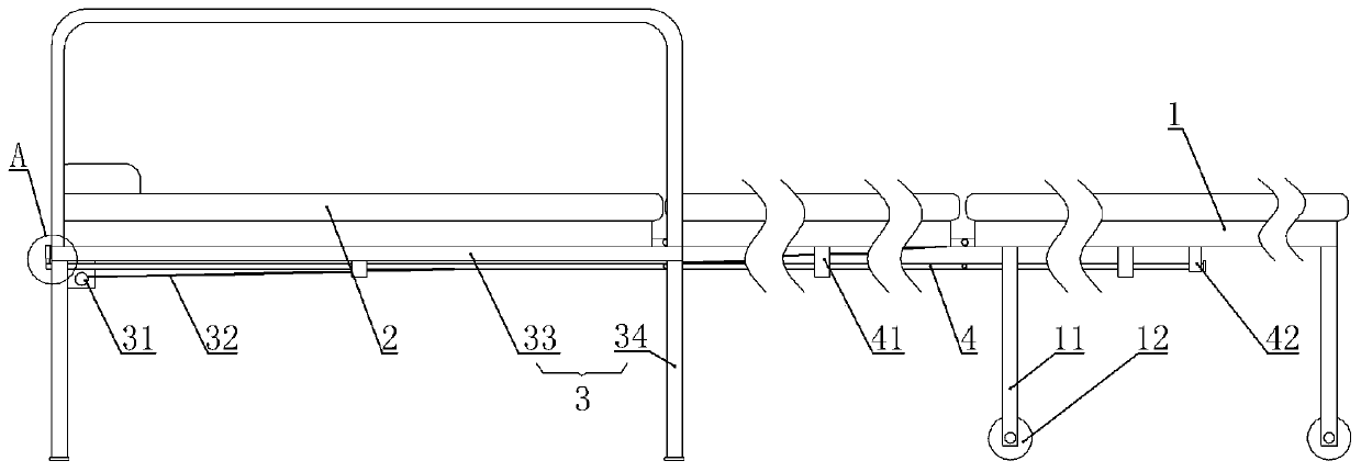
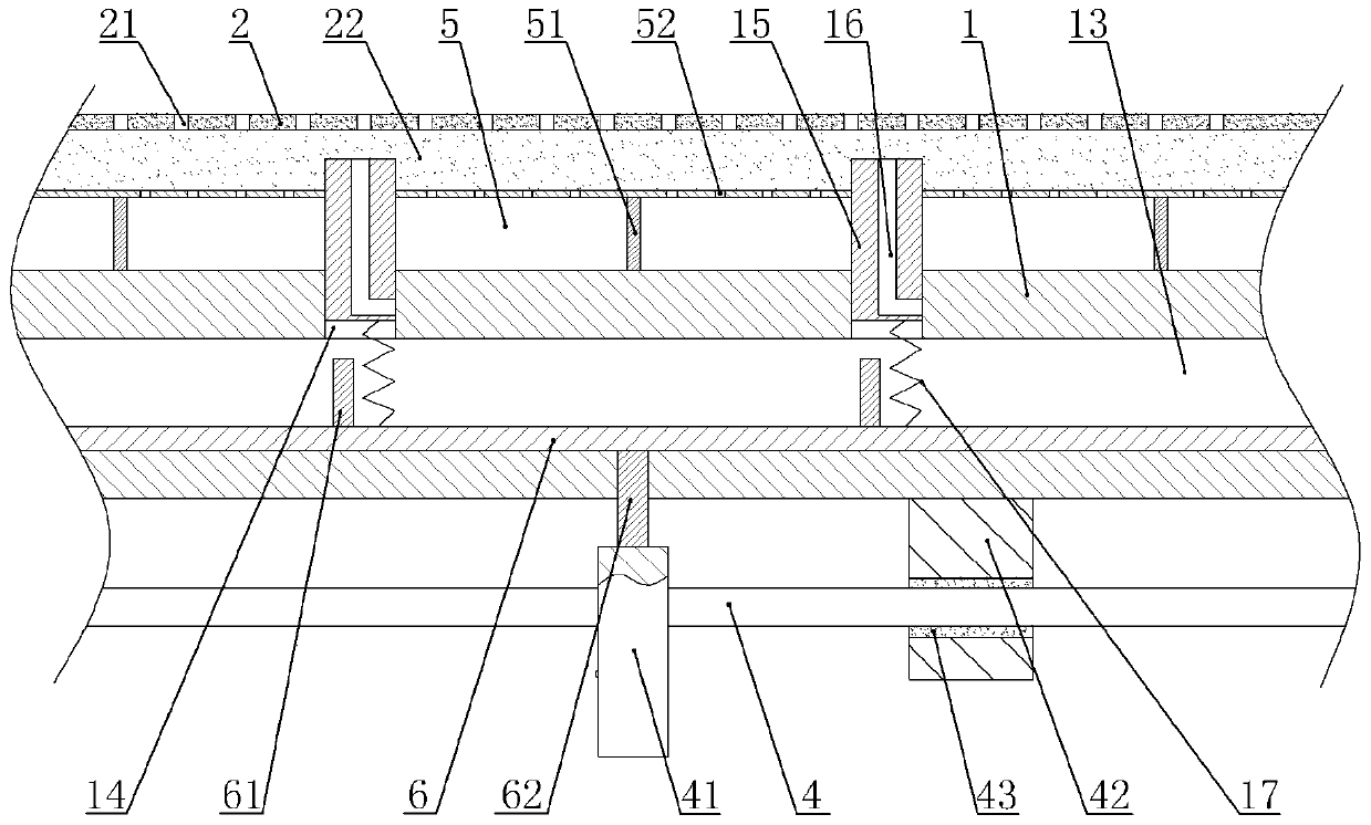
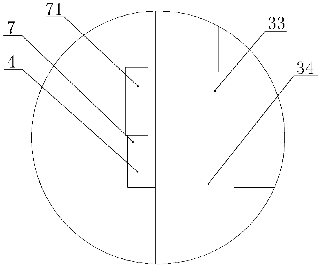
[0037] An automatic companion bed, such as figure 1 , figure 2 with image 3 As shown, it includes at least three bottom plates. The number of bottom plates in this embodiment is three. Adjacent bottom plates are hinged, and from right to left are the first bottom plate 1, the second bottom plate, and the third bottom plate. The first bottom plate 1, Both the second bottom plate and the third bottom plate are provided with a buffer layer on top. Taking the first bottom plate 1 as an example, the buffer layer in this embodiment includes a sponge layer 22 and an outer layer 2 located above the sponge layer 22. The outer layer in this embodiment The layer 2 is made of waterproof and breathable cloth material. The edges of the outer layer 2 and the sponge layer 22 are glued to the side wall of the first bottom plate 1, and the outer layer 2 is provided with a number of through holes 21.

[0038] The bottoms of the left and right ends of the first base plate 1 are vertically welded wi...

Embodiment 2

[0049] The difference from Example 1 is that Figure 4 As shown, the companion bed in this embodiment includes four bottom plates, the fourth bottom plate is located on the left side of the third bottom plate, and the right end of the fourth bottom plate is hinged to the left end of the third bottom plate, and the bottom of the fourth bottom plate is welded with a leg 11, this embodiment The roller 12 is not provided on the leg 11 on the fourth bottom plate in the fourth bottom plate, the rotating rod 4 and the cam 41 are also provided under the fourth bottom plate, and the cross bar 7 is located at the left end of the rotating rod 4 below the fourth bottom plate. In addition, a battery is fixed on the support frame 3 by bolts, and the battery is connected in series with the stepping motor.

[0050] The companion bed in this embodiment is folded in the form of two seat back-to-backs, and there is no need to connect the socket when the stepper motor works. The battery directly sup...


PUM


Abstract

The invention relates to the field of furniture and particularly discloses an automatic accompanying bed. The automatic accompanying bed comprises at least three bottom plates, wherein the adjacent bottom plates are hinged, a buffer layer is fixed to the top of each bottom plate, supporting legs are fixed to the bottom of the bottom plate at one side, and a supporting frame is hinged to the bottomof the bottom plate at the other side; a pull rope is fixed to the bottom plate where the supporting legs are fixed, and a stepping motor capable of rolling the pull rope is fixed to the supporting frame; a heating cavity is formed in each bottom plate, a plurality of hot air channels are formed in the top wall of each heating cavity, a piston is connected into each hot air channel in a verticalsliding mode, each piston is higher than the top of the corresponding bottom plate, a spring is fixed between each piston and the inner wall of the corresponding heating cavity, and each piston is provided with an exhaust channel which communicates with the corresponding heating cavity in the slide-down process; and each buffer layer is provided with a plurality of through holes, and each heatingcavity communicates with an air-in piece and a heating piece. According to the scheme, the accompanying bed can be unfolded slowly and automatically without being unfolded by manpower completely, andthe situation that a large sound is generated in the unfolding process is avoided.

Description

Technical field [0001] The invention relates to the field of furniture, in particular to an automatic companion bed. Background technique [0002] Accompanying beds can facilitate patients' family members to rest in the ward at night, and can be folded during the day, and will not hinder the walking of other personnel, doctors or nurses in the ward. At present, each hospital bed is equipped with at least one accompanying bed. The companion bed is in the shape of a seat when folded during the day. When used at night, it is necessary to manually push the lower ends of the folded parts away from each other to expand the companion bed into a bed shape. [0003] For example, the patent application number 201820633010.2 discloses a folding accompany bed chair, including a support frame, a back plate, a front back plate, and a seat plate. The support frame and the back plate are rotatably connected, and the back plate and the front The back board is connected in rotation, and the front b...

Claims


Application Information

Patent Timeline
IPC IPC(8): A47C13/00A47C19/12A47C21/04
CPCA47C13/00A47C19/12A47C21/048
Inventor 汤跃王红霞
Owner THE FIRST AFFILIATED HOSPITAL OF ARMY MEDICAL UNIV
Why Eureka
Try Eureka