
Spraying and cooling device

A spray cooling and processing device technology, applied in metal processing machinery parts, maintenance and safety accessories, metal processing equipment, etc., can solve the problem of inability to ensure cooling liquid injection, damage to tools, and inability to adjust the angle and height of spray cooling liquid in real time And other issues

Active Publication Date: 2020-01-03
FU DING ELECTRONICSAL TECH JIASHAN
View PDF6 Cites 0 Cited by
  • Summary
  • Abstract
  • Description
  • Claims
  • Application Information

AI Technical Summary

Problems solved by technology

The processing spray cooling liquid of the existing machine sprays the cooling liquid through the hose, and the position of the hose is fixed, and the angle and height of the spray cooling liquid cannot be adjusted in real time according to the change of the tool length, so that it cannot ensure that the cooling liquid is always sprayed on the tool. In turn, the tool cannot be cooled and the tool is damaged, which affects the processing efficiency and yield

Method used


Image

  • Spraying and cooling device
  • Spraying and cooling device
  • Spraying and cooling device

Examples


Embodiment Construction

[0016] The following will clearly and completely describe the technical solutions in the embodiments of the present invention with reference to the accompanying drawings in the embodiments of the present invention. Obviously, the described embodiments are only some of the embodiments of the present invention, not all of them. Based on the embodiments of the present invention, all other embodiments obtained by persons of ordinary skill in the art without making creative efforts belong to the protection scope of the present invention.

[0017] It should be noted that when an element is considered to be "connected" to another element, it may be directly connected to the other element or there may be an intervening element at the same time. When an element is said to be "disposed on" another element, it can be directly disposed on the other element or intervening elements may also be present.

[0018] Unless otherwise defined, all technical and scientific terms used herein have th...


PUM


Abstract

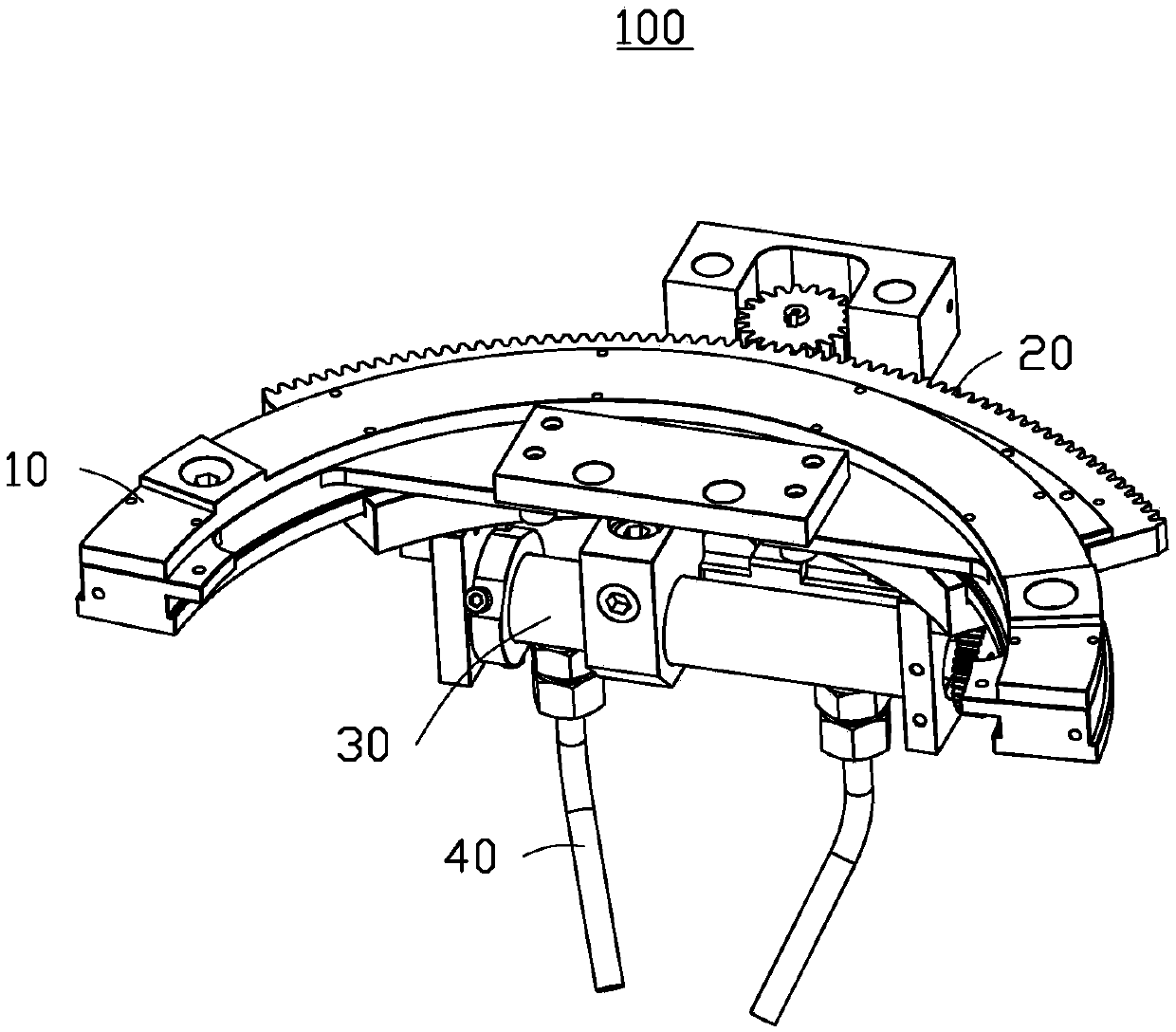
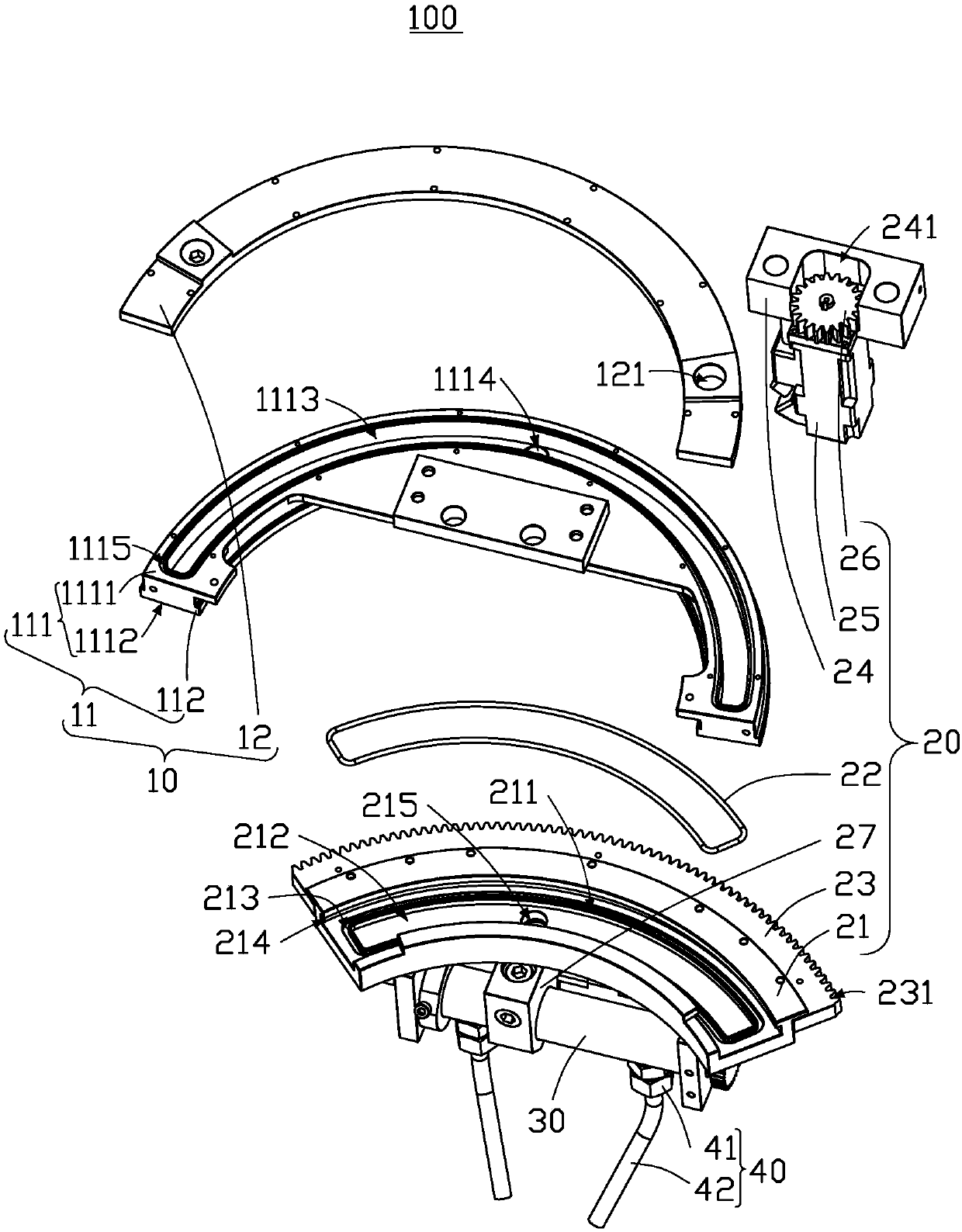
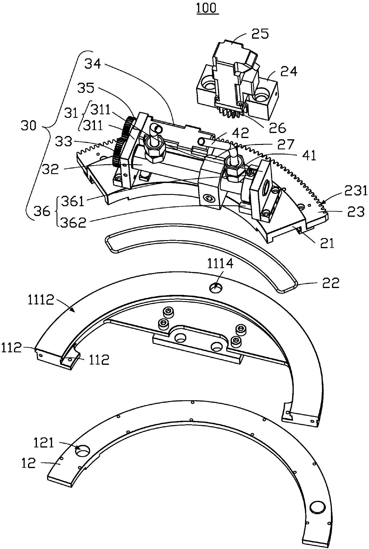
The invention provides a spraying and cooling device. The spraying and cooling device is used for spraying and cooling a cutter of a machining device. The spraying and cooling device comprises a fixing mechanism, a rotating mechanism, a swing mechanism and at least one spraying piece. The fixing mechanism comprises a fixing piece and a sealing piece. A containing groove is formed in the fixing piece. At least one through hole is formed in the containing groove. The rotating mechanism comprises a sliding piece, a rack, a rotating driving piece, a gear and a liquid injection piece. A guide groove, a liquid storage groove and a liquid injection hole are formed in the sliding piece. A biting tooth portion is arranged on the rack. The rack is arranged on the rotating driving piece and engaged with the biting tooth portion to drive the sliding piece to move. A penetrating hole and a connecting hole are formed in the liquid injection piece. The two ends of the connecting hole are correspondingly communicated with the penetrating hole and the liquid injection hole. The swinging mechanism comprises a fixing frame, a swinging shaft and a swinging driving piece. A containing cavity, a liquidinlet groove, at least one liquid inlet hole and at least one liquid outlet hole are formed in the swinging shaft. The swinging driving piece drives the swinging shaft to rotate to adjust the sprayingangle of each spraying piece. The spraying and cooling device is convenient to adjust.

Description

technical field [0001] The invention relates to a spray cooling device, in particular to a spray cooling device which is convenient for cooling a processing tool of a processing device. Background technique [0002] CNC (Computer numerical control) machines will generate a large amount of cutting heat during processing, which will increase the temperature of the tool, workpiece, and even the machine tool. In order to reduce tool wear and lower the temperature of the processing part, cooling liquid is often used to spray the tool . The processing spray cooling liquid of the existing machine sprays the cooling liquid through the hose, and the position of the hose is fixed. The angle and height of the spray cooling liquid cannot be adjusted in real time according to the change of the tool length, so that it cannot ensure that the cooling liquid is always sprayed on the tool. In turn, the tool cannot be cooled and the tool is damaged, thereby affecting the processing efficiency...

Claims


Application Information

Patent Timeline
IPC IPC(8): B23Q11/10
CPCB23Q11/1076
Inventor 贾见士戚家联桂洋付军李杰杨明陆
Owner FU DING ELECTRONICSAL TECH JIASHAN
Learn More