Vision-based robot automatic calibration method, equipment and storage medium

An automatic calibration and robot technology, applied in the direction of manipulators, program-controlled manipulators, manufacturing tools, etc., can solve problems such as troublesome and cumbersome operations

Active Publication Date: 2020-01-03
SUZHOU UNIV
View PDF11 Cites 14 Cited by
  • Summary
  • Abstract
  • Description
  • Claims
  • Application Information

AI Technical Summary

Problems solved by technology

[0016] From the perspective of the calibration process, it is necessary to print a nine-point calibration paper of appropriate size according to the camera's field of view, install a calibration pin at the end of the robot, and manually teach nine robot coordinates, which is cumbersome and cumbersome to operate.

Method used


Image

  • Vision-based robot automatic calibration method, equipment and storage medium
  • Vision-based robot automatic calibration method, equipment and storage medium
  • Vision-based robot automatic calibration method, equipment and storage medium

Examples


Embodiment

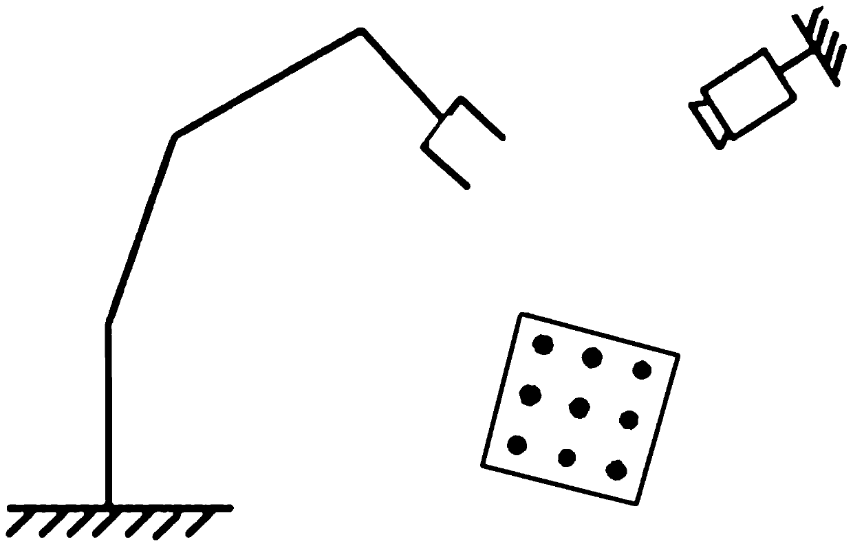
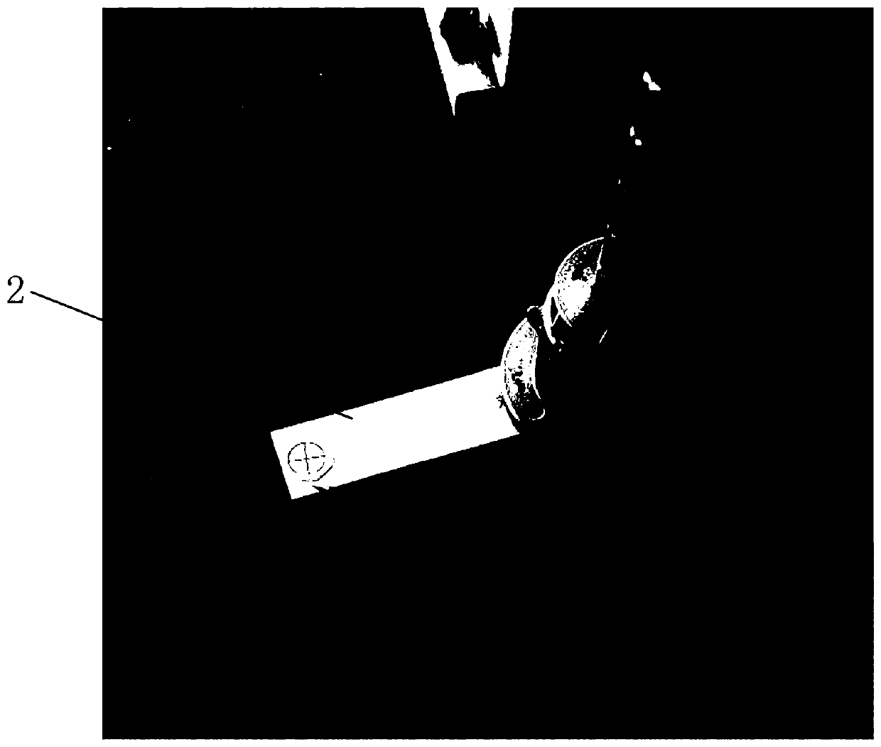
[0045] This embodiment discloses a vision-based automatic calibration method for a robot. The calibration method needs to use a robot, a camera and a MARK point. The MARK point is fixed at the end of the robot (that is, the action execution end of the robot), refer to figure 2 As shown, the MARK point "+" is set on the marking plate 2, and the marking plate 2 is installed at the end of the robot. In actual use, the marking plate 2 can be fixed at the end of the robot by pasting or negative pressure adsorption. Among them, the MARK point is set according to the requirement that it is at the same level as the detected workpiece. The position of the above-mentioned camera is fixed, and the movement of the above-mentioned robot makes the MARK point move in the camera field of view. The above-mentioned camera is used to observe the attitude of the MARK point and record the pixel coordinates of the MARK point in the camera coordinate system.

[0046] After introducing the MARK poi...


PUM


Abstract

The invention discloses a vision-based robot automatic calibration method, equipment and a storage medium. A MARK point is fixed at the tail end of a robot, and the attitude of the MARK point is observed with a camera. The calibration method includes the steps that (1) the robot moves by nine step lengths to obtain nine point locations which are in a 3*3 manner, position coordinates of the tail end of the robot in a robot coordinate system and pixel coordinates of the MARK point in the camera coordinate system are recorded in correspondence with all the point locations, the recorded position coordinates and pixel coordinates of the nine point locations are processed according to a nine-point calibration method, and a mapping matrix X3*3 between the robot coordinate system and the camera coordinate system is obtained; (2) according to the mapping matrix X3*3, a tool coordinate system T(Xt,Yt,theta) is calculated and established with the MARK point as the center; and (3) a conversion relationship between the pixel coordinates and the position coordinates of MARK point is calculated according to the tool coordinate system T and the mapping matrix X3*3, and nine-point calibration of the camera coordinate system to the robot coordinate system is achieved. The calibration method does not require manual teaching, simplifies the calibration process and effectively improves the calibration speed and the calibration accuracy.

Description

technical field [0001] The invention relates to the technical field of machine calibration, in particular to a vision-based automatic calibration method, equipment and storage medium for a robot. Background technique [0002] In conventional 2D vision applications, take eye-to-hand as an example, refer to figure 1 As shown, the camera is fixedly installed relative to the manipulator, so the camera coordinate system is fixed relative to the workpiece coordinate system. The purpose of the nine-point calibration is to obtain the conversion matrix between the pixel coordinates and the end coordinates of the manipulator. [0003] Assuming that the image coordinates are (x, y) and the manipulator coordinates are (X, Y), the manipulator coordinates can be regarded as obtained from the image coordinates through rotation and translation, as shown in formula (1): [0004] [0005] And then there is, [0006] [0007] For different points, there are: [0008] [0009] Writ...

Claims


Application Information

Patent Timeline
Patent Type & Authority Applications(China)
IPC IPC(8): B25J9/16
CPCB25J9/1697
Inventor 谢小辉张秀安
Owner SUZHOU UNIV
Why Eureka
Try Eureka