Online water examining technology for blast furnace cooling wall and water tank applying the same

A cooling wall and water tank technology, applied in cooling devices, inspection devices, etc., can solve the problems of easy misjudgment, high labor intensity, and lack of science, and achieve the effect of improving accuracy

Active Publication Date: 2020-01-03
SGIS SONGSHAN CO LTD
View PDF6 Cites 1 Cited by
  • Summary
  • Abstract
  • Description
  • Claims
  • Application Information

AI Technical Summary

Problems solved by technology

Relying on the personal experience of the technicians to check the water on the cooling wall online, due to the different experience of the technicians, the accuracy of the water check is low, and it is prone to misjudgment, which is not scientific enough and the labor intensity is high

Method used


Image

  • Online water examining technology for blast furnace cooling wall and water tank applying the same

Examples


Embodiment 1

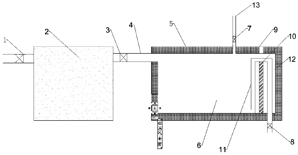
[0029] See figure 1 : A blast furnace cooling stave 2 online water checking process, the process flow is as follows:

[0030] a) Use toughened glass on the tank wall to make a sealed portable water tank 5. The water tank 5 is 1000mm long, 500mm high, and 500mm wide; a hole is made on the side of the water tank 5 at a height of 420mm, and the diameter of the hole is the same as that of the cooling wall 2. The same size is 50mm; an isolation plate 10 is installed in the water tank 5. The isolation plate 10 is in tangential contact with the three sides of the water tank 5. The height of the isolation plate 10 is 420mm. The isolation plate 10 divides the water tank 5 into the reservoir 6 and the reservoir. The volume of the air chamber 12, the reservoir 6 and the air reservoir 12 is 4:1. A hole is opened below the gas storage chamber 12 with a diameter of 30mm. A drain valve 8 is installed. The valve is a ball valve. The rubber pipe 11 is connected to the reservoir 6 through the iso...

Embodiment 2

[0041] b) In the smelting state of the blast furnace, the pressure in the furnace is 408KPa, the inlet pressure of the cooling stave 2 is 1200KPa, close the inlet valve of the cooling stave 2 to make the inlet pressure 320KPa, and connect the outlet pipe 4 of the cooling stave 2 to the water tank 5. Let the water from the cooling wall 2 flow into the water tank 5.

[0042] c) When the water tank 5 starts to store water, the gas detector 9 shows that the gas detection value is 0ppm. When the water level of the water tank 5 reaches the isolating plate 10, the gas detector 9 measures the gas value of 0ppm, and the cooling wall 2 has no leakage .

[0043] d) Open the drain valve 8 to gradually drain the water in the reservoir 6, and at the same time disconnect the water outlet pipe 4 of the cooling wall 2 from the water tank 5.

[0044] e) Open the pressure relief valve 7 to relieve the pressure in the water tank 5.

[0045] Use effect: by checking the water of the cooling stave 2 in the...


PUM

PropertyMeasurementUnit
diameteraaaaaaaaaa

Abstract

The invention relates to an online water examining technology for a blast furnace cooling wall. The technology comprises the following steps that a cooling wall water inlet valve is turned down according to the pressure inside a furnace in the blast furnace smelting state, so that the water inlet pressure is smaller than the pressure inside the blast furnace, a cooling wall water outlet pipe is inbutt-joint with a water tank, and water inside the cooling wall is made to flow into the water tank; whether or not a coal gas detector has a coal gas detection value in the process is observed; whenthe water level inside the water tank is increased to an isolation plate, water inside a reservoir is drained out step by step, meanwhile, the cooling wall water outlet pipe is disconnected from thewater tank, and pressure relief is performed inside the water tank; if the coal gas detector displays a coal gas value, a kindling material is introduced, and emitted coal gas is combusted. Water examination can be performed on the cooling wall under the production state, whether or not the cooling wall leaks water can be judged precisely, the defect that existing water examination is judged by means of artificial experience is changed, and the online water examining accuracy of the blast furnace cooling wall is improved.

Description

Technical field [0001] The invention belongs to the technical field of blast furnace detection, and relates to an online water checking process for cooling staves of a blast furnace and a water tank applied to the process. Background technique [0002] The structure of the blast furnace type generally includes: the outer shell is made of steel plate, which is called the furnace shell; the cooling stave is installed in the furnace shell; the protective brick is built in the cooling stave; the filling between each layer Ramming material. [0003] The cooling stave of the blast furnace is generally divided into more than 10 layers from the bottom of the furnace to the throat, and dozens of cooling staves are installed along the circumference of the furnace body to ensure the safety of the blast furnace body structure. [0004] The cooling method adopted for the blast furnace stave is mainly as follows: high-pressure cooling water is introduced at one end of the stave, and the cooling w...

Claims


Application Information

Patent Timeline
Patent Type & Authority Applications(China)
IPC IPC(8): C21B7/10C21B7/24
CPCC21B7/103C21B7/24
Inventor 陈生利卢永凯师瑞虹蔡琳陈开泉李明星陈胜黄恺姜叶邓娟
Owner SGIS SONGSHAN CO LTD
Why Eureka
Try Eureka