

Pouring device, lining trolley and pouring technology
A technology for lining trolleys and pouring pipes, which can be used in wellbore lining, tunnel lining, shaft equipment, etc., and can solve problems such as voiding
- Summary
- Abstract
- Description
- Claims
- Application Information
AI Technical Summary
Problems solved by technology
Method used
Image

Examples
Embodiment 1
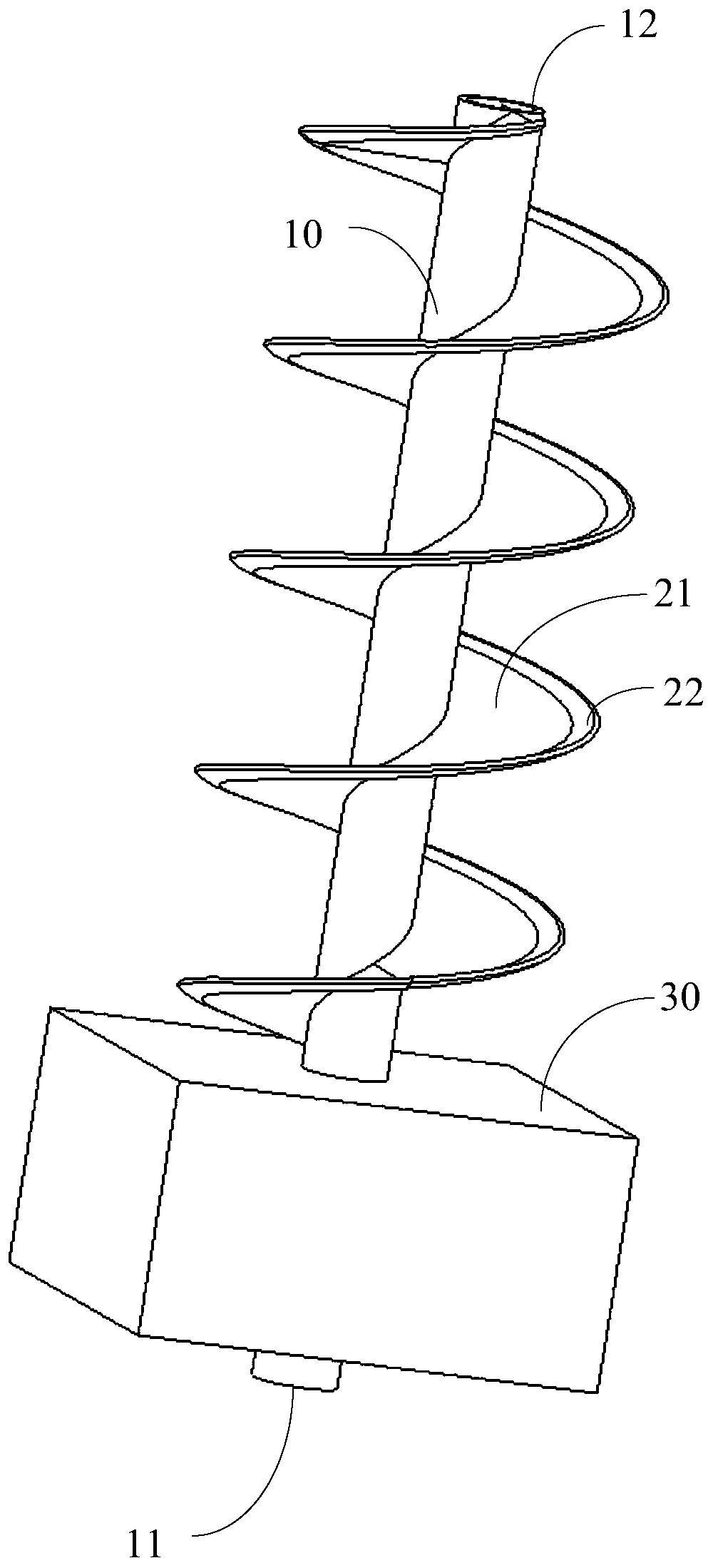
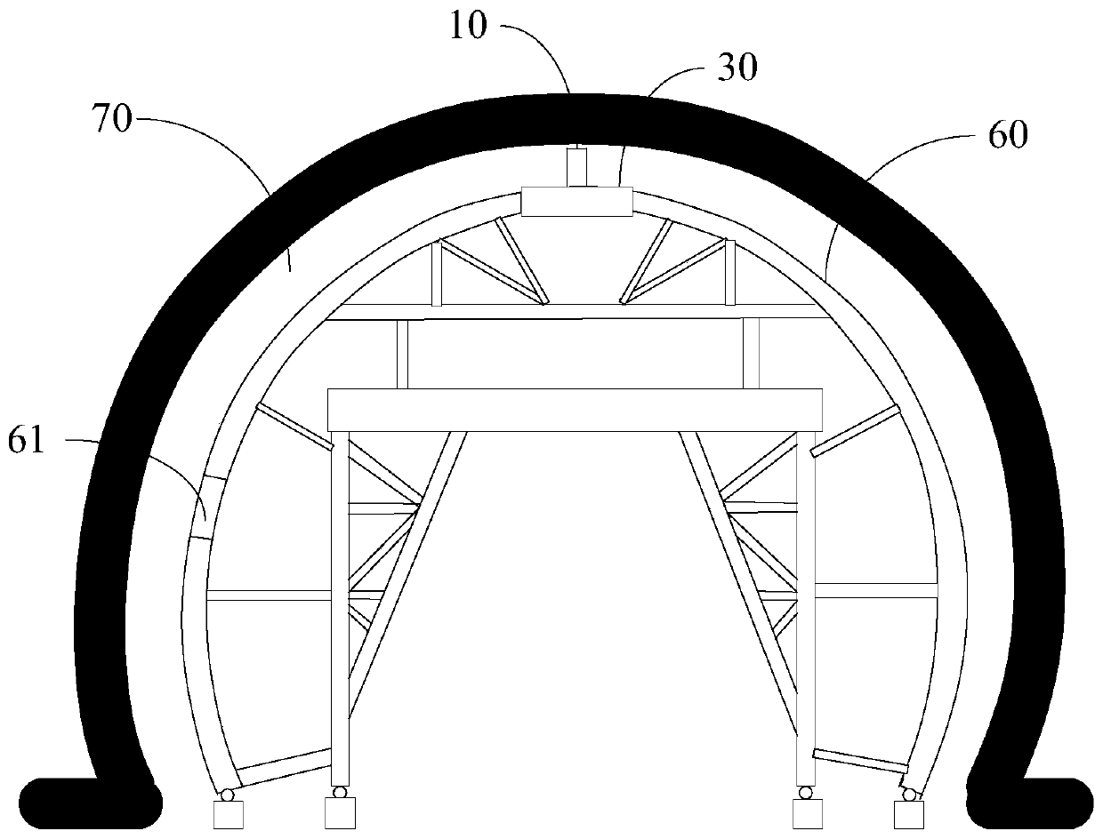
[0026] The present invention proposes a pouring device, with reference to Figure 1 to Figure 3 , the pouring device is applied on the lining trolley, and the lining trolley includes an arc formwork 60, and the arc formwork 60 is provided with a pouring window 61, and the pouring device includes a The fixing seat 30 , the pouring pipe 10 arranged on the fixing seat 30 , the helical piece 21 arranged on the outer periphery of the pouring pipe 10 , and the driving assembly 50 for driving the helical piece to rotate.
[0027] In this embodiment, in the secondary lining of the trolley, a certain distance is maintained between the arc steel form and the construction surface of the inner wall of the tunnel, and end formwork is provided at both ends of the arc formwork 60 to form a pouring cavity together. 70. The present invention is equipped with a pouring device. In the pouring device, the fixed seat 30 is arranged correspondingly to the pouring window 61. The pouring pipe 10 is ...
Embodiment 2
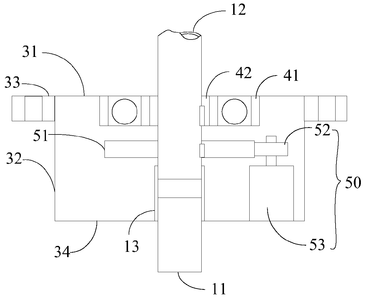
[0034] refer to Figure 4 , in this embodiment, the lower end of the pouring pipe 10 is provided with a mounting step 13, and the outer wall of the pouring pipe 10 is provided with a first bearing 41, and the outer ring of the first bearing 41 is provided with a rotating seat 23, so that the mounting seat 23 It is rotatably connected with the pouring pipe 10. The installation seat 23 is arranged on the installation step 13, and the top of the rotating seat 23 is also spirally extended upwardly around the pouring pipe 10 to provide a spiral piece 21, the spiral piece 21 extends to the concrete outlet 12, and the spiral piece 21 and the pouring pipe 10 The outer walls are not in direct contact. A second bearing is arranged between the fixed seat and the rotating seat 23, whereby the spiral piece 21 is rotatably connected with the fixed seat. The driving assembly can be driven by a motor, and the driving motor is arranged on the fixed seat, and the transmission parts can be sel...
PUM
 Abstract
Description
Claims
Application Information