A kind of water spraying system and control method of lng vaporizer

A vaporizer and water spray technology, applied to indirect heat exchangers, heat exchanger types, deicing, etc., can solve problems such as long time consumption, prolonged ice melting time, lack of automatic control of water temperature, etc., to achieve The effect of improving utilization rate, improving heat exchange efficiency and speeding up ice melting speed

Active Publication Date: 2021-01-05
湛江新奥燃气有限公司
View PDF9 Cites 0 Cited by
  • Summary
  • Abstract
  • Description
  • Claims
  • Application Information

AI Technical Summary

Problems solved by technology

The process of melting ice takes a long time, and when the temperature is low in winter, the time for ice to melt is greatly prolonged
The existing gasifier spray technology does not make full use of water resources and heat energy, and also lacks automatic control of water temperature

Method used


Image

  • A kind of water spraying system and control method of lng vaporizer
  • A kind of water spraying system and control method of lng vaporizer
  • A kind of water spraying system and control method of lng vaporizer

Examples


Embodiment 1

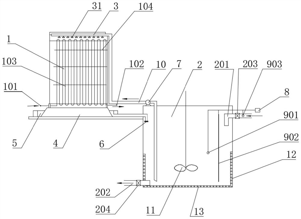
[0047] A kind of LNG vaporizer 1 water spraying system, such as figure 1 As shown, it includes an LNG vaporizer 1 , a circulating water pool 2 , a monitoring device 9 , a controller 8 , and a spraying device 3 .

[0048] The LNG vaporizer 1 is arranged on a base 4, and the base 4 is arranged on the side of the circulating pool 2, and a water diversion groove 5 is arranged around the base 4, and the water diversion groove 5 is connected to the The circulating water pools 2 are connected, and the spray water flows back to the circulating water pool 2 through the water diversion tank 5 .

[0049] The upper part of the circulating pool 2 is provided with a water inlet pipe 201, and the lower part is provided with a drain pipe 202, and the water inlet pipe 201 and the drain pipe 202 are respectively provided with valves, which are respectively an inlet pipe valve 203 and a drain pipe valve 204; The side wall and the bottom of the pool 2 are also independently installed with heatin...

Embodiment 2

[0071] The rest are the same as in Embodiment 1, the difference is that no water blocking layer 104 is set in the heat exchange tube group, as Figure 5 , and the fins 1031 on the heat exchange tube 103 are in a spiral shape from top to bottom along the outer wall of the heat exchange tube 103, the helix angle is 45-80°, and the fins 1031 are spiral-like spirals, from top to bottom The distance between the lower adjacent spirals increases sequentially, so that the residence time of the spray water gradually shortens from top to bottom, and the heat exchange rate is improved.

Embodiment 3

[0073] Others are the same as in Embodiment 2, the fins 1031 on the heat exchange tube 103 are in a spiral shape from top to bottom along the outer wall of the heat exchange tube 103, the difference is that the helix angle is 15-45°. The inner wall of the heat exchange tube 103 is as Figure 6 , Figure 7 smooth inner wall as shown, or as Figure 8 , Figure 9 The spiral shown is concentric with the fins 1031 on the outer wall. The spiral inner wall increases the contact area between the liquefied gas and the inner wall, reduces the flow velocity of the liquefied gas, and at the same time creates turbulent flow, which is beneficial to heat exchange.


PUM


Abstract

An LNG gasifier water spraying system comprises an LNG gasifier, a circulation water pool, a monitor device, a controller and a spraying device. The LNG gasifier is arranged on a base. A water guide trough connected with the circulation water pool is arranged around the base. Heating devices are independently mounted on the side wall and the bottom of the circulation water pool. The monitor devicecomprises a first temperature detector on a water inlet pipe, a second temperature detector in the circulation water pool and a liquid level detector. The controller controls opening and closing of avalve and the heating devices according to transmitted temperature signals and liquid level signals. Multiple water stop layers are arranged in the middle of a heat exchange pipe set on the gasifier.Fins of heat exchange pipes are spirally distributed in different forms. By means of the LNG gasifier water spraying system, heat exchange efficiency is greatly improved, the intelligent control method is adopted, the relations between water inlet heat, consumed heat, the water quantity and electric energy are balanced, natural water heat energy is utilized to the greatest extent, meanwhile, normal use is not influenced, automatic control can be achieved, and control precision is high.

Description

technical field [0001] The invention relates to the technical field of gasification of liquefied natural gas (LNG), in particular to a water spray system and a control method of an LNG gasifier. Background technique [0002] The air-temperature gasifier is a heat exchange device that uses natural convection of air to heat low-temperature LNG to gasify it into a normal temperature gas. The existing LNG air-temperature vaporizers on the market are made of aluminum finned tubes connected at a certain distance. During use, the outer surface of the vaporizer is easy to freeze. If the ice layer is too thick, it is not conducive to the vaporizer. normal use. In actual use, after the gasifier has accumulated a certain thickness of ice, it is necessary to stop using the gasifier, and the gasifier can be used only after the ice layer on the surface of the gasifier is melted by the atmospheric temperature. The process of melting ice takes a long time, and when the temperature is low ...

Claims


Application Information

Patent Timeline
Patent Type & Authority Patents(China)
IPC IPC(8): F28F27/00F28D1/047F28F1/36F28F17/00
CPCF28D1/0478F28F1/36F28F17/00F28F27/00F28F2265/14
Inventor 吴俊铿梁锦秀虢德鹤何丹林土志莫嘉杰
Owner 湛江新奥燃气有限公司
Why Eureka
Try Eureka