Combined system for converting single-phase electricity into three-phase electricity

A technology of single-phase electricity and three-phase electricity, applied in the direction of electrical components, circuit devices, AC network circuits, etc., to achieve the effect of easy implementation and good versatility

Pending Publication Date: 2020-01-03
SOUTHWEST JIAOTONG UNIV
View PDF0 Cites 0 Cited by
  • Summary
  • Abstract
  • Description
  • Claims
  • Application Information

AI Technical Summary

Problems solved by technology

[0006] The purpose of the present invention is to provide a combined single-phase power-to-three-phase power system, which can effectively solve the technical problems when single-phase line users need three-phase power consumption

Method used


Image

  • Combined system for converting single-phase electricity into three-phase electricity
  • Combined system for converting single-phase electricity into three-phase electricity
  • Combined system for converting single-phase electricity into three-phase electricity

Examples


Embodiment 1

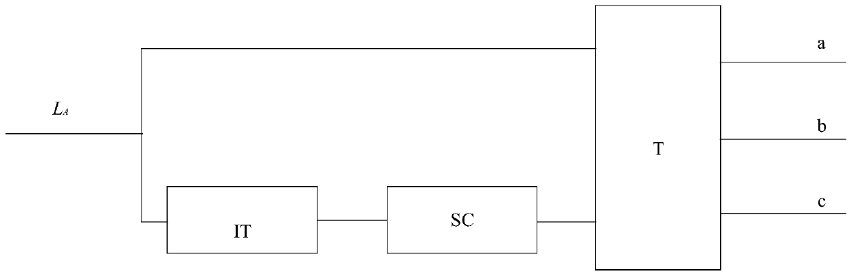
[0026] Such as figure 1 As shown, the embodiment of the present invention provides a combined single-phase power-to-three-phase power system, wherein the system includes a transmission line L A , isolation transformer IT, three-port power converter SC and three-phase transformer T; the input end of the isolation transformer IT and the transmission line L A Connection; three-phase transformer T star winding and three-port power converter SC and transmission line L respectively A Connection, the a terminal, b terminal and c terminal of the three-phase transformer T delta winding are connected to the low-voltage distribution network with the neutral point grounded.

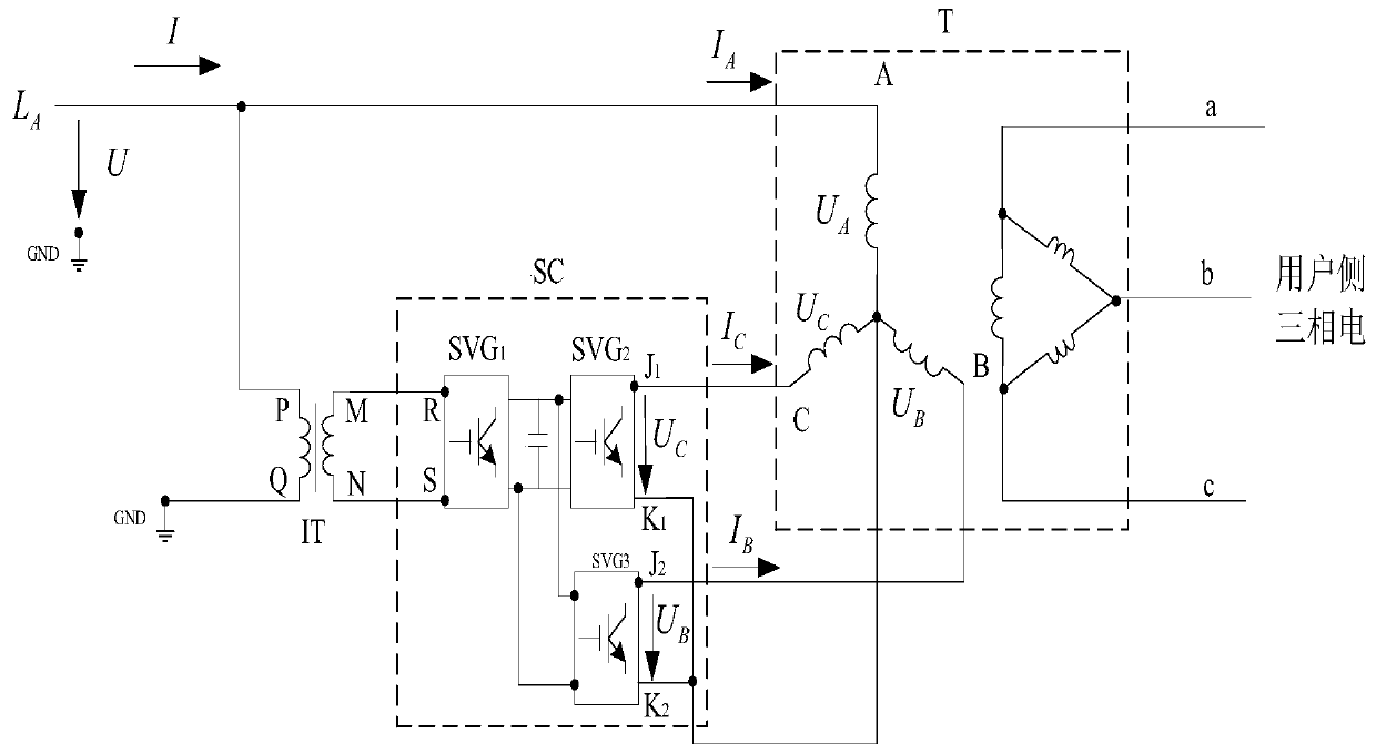
[0027] Such as figure 2 As shown, the P terminal of the input terminal of the isolation transformer IT is connected to the power line L A connection, the Q terminal of the isolation transformer IT is grounded; the M terminal and the N terminal of the output end of the isolation transformer IT are respectively con...

Embodiment 2

[0032] Such as figure 1 As shown, the embodiment of the present invention provides a combined single-phase power-to-three-phase power system, wherein the system includes a transmission line L A , isolation transformer IT, three-port power converter SC and three-phase transformer T; the input end of the isolation transformer IT and the transmission line L A Connection; three-phase transformer T star winding and three-port power converter SC and transmission line L respectively A Connection, the a terminal, b terminal and c terminal of the three-phase transformer T delta winding are connected to the low-voltage distribution network with the neutral point grounded.

[0033] Such as Figure 4 As shown, the main difference between the embodiment of the present invention and the above-mentioned embodiment is: the Q terminal of the isolation transformer IT of the system and the return line L B connect. Other structures and features are the same as those in the first embodiment ab...


PUM


Abstract

The invention discloses a combined system for converting single-phase electricity into three-phase electricity, and relates to the technical field of power grid power supply and distribution. The terminal M and the terminal N of the output end of an isolation transformer IT are respectively connected with the terminal R and the terminal S of the input end of a three-port power supply converter SC;the terminal B of the star-shaped winding of a three-phase transformer T is connected with the terminal J2 of the output end of the three-port power supply converter SC, and the terminal C of the star-shaped winding of the three-phase transformer T is connected with the terminal J1 of the output end of the three-port power supply converter SC; the central point of the star-shaped winding of the three-phase transformer T is respectively connected with the terminal K1and the terminal K2 of the output end of the three-port power supply converter SC; and the terminal Q of the isolation transformer IT is connected with a return line LB, and the terminal a, the terminal b and the terminal c of the triangular winding of the three-phase transformer T are connected with a low-voltage power distribution network with a grounded neutral point.

Description

technical field [0001] The invention relates to the technical field of electric power grid power supply and distribution. Background technique [0002] Users in the field of low-voltage power distribution in my country generally use single-phase power supply. When users need to use three-phase power, they need to re-erect power lines, which is very troublesome and takes a long time; Two-phase transmission lines, single-phase transformers are connected to users, which is more economical and does not take up space, but some users need three-phase power. In particular, the user needs to use the three-phase power supply for a short period of time due to special reasons, and the time for erecting a new three-phase line is not allowed. If the power quality of the grid allows, the three-phase power supply can be provided relatively easily, which will have a greater impact economic and social value. [0003] In the power distribution system, due to long-term mechanical force, elect...

Claims


Application Information

Patent Timeline
Patent Type & Authority Applications(China)
IPC IPC(8): H02J3/00H02J3/18H02M5/14H02M5/458
CPCH02J3/00H02J3/1842H02M5/14H02M5/4585Y02E40/30
Inventor 易东李群湛黄小红解绍锋郭锴张丽艳
Owner SOUTHWEST JIAOTONG UNIV
Why Eureka
Try Eureka