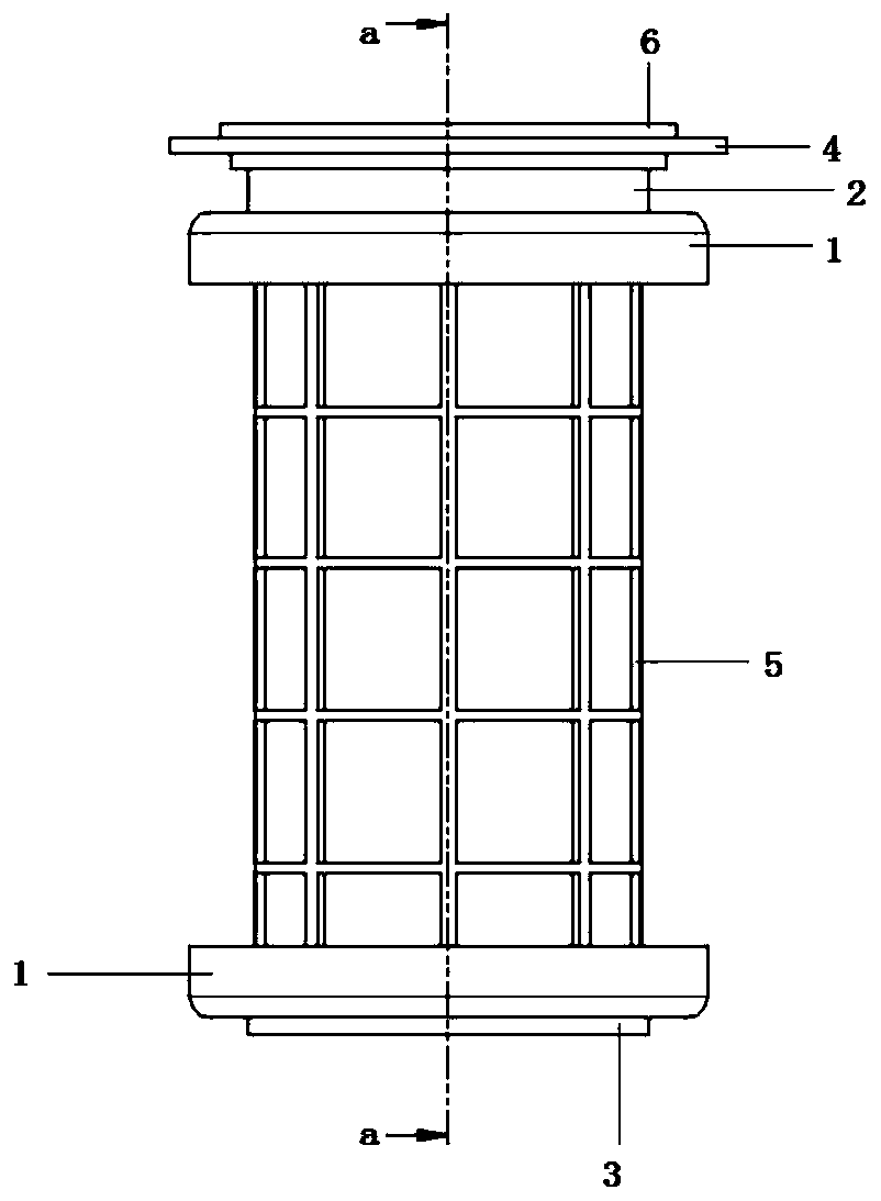
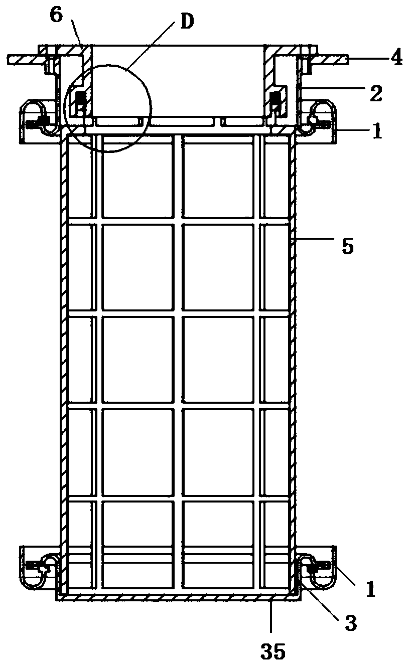
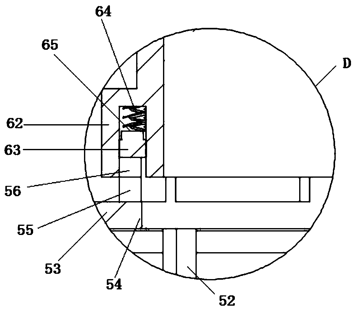
Filter bag structure of pulse dust collector

A technology of pulse dust collector and filter bag, which is applied in the direction of dispersed particle filtration, chemical instruments and methods, and separation of dispersed particles. It can solve the problems of difficult filter bag shaping, filter bag damage, and straight-through, so as to reduce wear and prolong service life. Effect

Inactive Publication Date: 2020-01-07
安徽华宇机械制造有限公司
View PDF0 Cites 0 Cited by
  • Summary
  • Abstract
  • Description
  • Claims
  • Application Information

AI Technical Summary

Problems solved by technology

[0002] With the continuous enhancement of people's awareness of environmental protection, pulse jet flat bag dust collectors are used more and more widely. As the key components of dust collectors, filter bags are connected to the dust chamber and clean air chamber of dust collectors. If the seal is not good, the dust chamber and the clean air chamber of the dust collector will be directly connected, which will affect the dust removal effect of the dust collector
Because the filter bag itself is supported by filter cloth, it is easy to deform in the hand, and it is often difficult to shape the filter bag during use. Therefore, the filter bag is easy to contact or even rub against the filter bag bracket supporting the filter bag under the action of wind speed during use, and it is easy to wear for a long time. damage to the filter bag

Method used


Image

  • Filter bag structure of pulse dust collector
  • Filter bag structure of pulse dust collector
  • Filter bag structure of pulse dust collector

Examples


Embodiment Construction

[0032] The following will clearly and completely describe the technical solutions in the embodiments of the present invention with reference to the accompanying drawings in the embodiments of the present invention. Obviously, the described embodiments are only some, not all, embodiments of the present invention. Based on the embodiments of the present invention, all other embodiments obtained by persons of ordinary skill in the art without creative efforts fall within the protection scope of the present invention.

[0033] In describing the present invention, it is to be understood that the terms "opening", "upper", "lower", "thickness", "top", "middle", "length", "inner", "surrounding" etc. Indicating orientation or positional relationship is only for the convenience of describing the present invention and simplifying the description, and does not indicate or imply that the components or elements referred to must have a specific orientation, be constructed and operated in a sp...


PUM


Abstract

The invention discloses a filter bag structure of a pulse dust collector, and relates to the technical field of dust collectors. The filter bag structure comprises a filter bag bracket and a filter bag body arranged on the outer side of the filter bag bracket; the filter bag bracket comprises a plurality of support rods distributed in a circumferential shape, the plurality of support rods are sequentially provided with a plurality of support rings from top to bottom, the inner side of one support ring positioned at the end part of the filter bag bracket is connected with a connecting ring through a plurality of connecting blocks, and the upper surface of the connecting ring is connected with a baffle ring through a plurality of support blocks; the filter bag body is of a cylindrical structure, the filter bag body comprises a filter cloth body, the filter cloth body is formed by sewing filter cloth and is of a circular-tube-shaped structure, and a first annular fixing structure and a second annular fixing structure are arranged at two ends of the filter cloth body respectively. Through cooperative use of the filter bag bracket, the first annular fixing structure and the second annular fixing structure, the abrasion of the filter bag bracket to the filter bag is prevented and reduced during use.

Description

technical field [0001] The invention belongs to the technical field of dust collectors, in particular to a filter bag structure of a pulse dust collector. Background technique [0002] With the continuous enhancement of people's awareness of environmental protection, pulse jet flat bag dust collectors are used more and more widely. As the key components of dust collectors, filter bags are connected to the dust chamber and clean air chamber of dust collectors. If the seal is not good, the dust chamber and the clean air chamber of the dust collector will be directly connected, which will affect the dust removal effect of the dust collector. Because the filter bag itself is supported by filter cloth, it is easy to deform in the hand, and it is often difficult to shape the filter bag during use. Therefore, the filter bag is easy to contact or even rub against the filter bag bracket supporting the filter bag under the action of wind speed during use, and it is easy to wear for a ...

Claims


Application Information

Patent Timeline
Patent Type & Authority Applications(China)
IPC IPC(8): B01D46/06
CPCB01D46/06
Inventor 李明杰
Owner 安徽华宇机械制造有限公司
Why Eureka
Try Eureka