Air bearing for use as a seal

a technology of air bearings and seals, applied in the field of seals, can solve the problems of large flows, wear grooves in the shaft, wear and leakage, etc., and achieve the effects of reducing friction wear and heat generation, stable and reliable, and easy adjustmen

Active Publication Date: 2014-06-17
NEW WAY MACHINE COMPONENTS
View PDF86 Cites 43 Cited by
  • Summary
  • Abstract
  • Description
  • Claims
  • Application Information

AI Technical Summary

Benefits of technology

[0008]Objects of the invention include: to provide more reliable gas seal and mechanical seal surfaces by teaching robust ways of; employing externally pressurized air bearing technology to create high pressures in noncontact sealing gaps; prevent or reduce wear and heat buildup between faces that are meant to run in contact or that may make occasional contact; teach how the combination of bearing and seal technology can dramatically simplify the sealing of rotating equipment and to prevent “hang ups” which is a failure of the compliance or biasing mechanism to keep the faces pressed against each other.
[0009]Modern Air bearing technology when applied to Turbo equipment has very interesting applications for replacing conventional bearings and seals (eliminating oil, improving efficiency, reducing noise).
[0010]Seals and counter surfaces designed to use one of two opposing sealing surfaces as a porous media to restrict externally supplied hydrostatic pressure into an air bearing gap between the surfaces. This technology would apply to replacing packing in large agitators, mixers or refiners; at the lower end of the seal continuum listed above and mechanical or dry gas seals on the higher end. One embodiment is the blade runner which is particularly well-suited to aero engine sealing enabling a dramatic reduction in friction, wear, and noise with improved stage sealing. Additionally the rotating mass and axial length of the seal is dramatically reduced. Another embodiment taught is the balance force face seal where mechanical face seals would run in contact with virtually no contact force even though there may be thousands of pounds of closing force.
[0017]As non-contact seals, they have no coulomb friction and no wear. There is viscous shear friction in the air film but this is orders of magnitude less than the bearing friction. This bodes well for reduced energy consumption and allows for strong green sales arguments. Radial and thrust or face type seals are both possible.
[0018]Even though they are noncontact they are mechanically coupled to their counter surface via the compression of the air film. As in the example of FIG. 3B, the bushing seal is supported by the spinning shaft it is sealing on. This allows for eliminating alignment issues found in labyrinth seals. This is a self-aligning capability. The seal is stationery with respect to the stator and connected to it through some sort of a flexible bellow, diaphragm or O-ring as examples of compliant mounts. Bearing isolators from manufacturers such as GGB, Waukesha and Crane are examples of the current state of the art in compliant mounts that allow for the shifting of the center of the shaft and also for angular changes of the shaft. The bearing isolators mentioned above use copious quantities of compressed air or injection fluid into a gap as they do not use compensated hydrostatic bearing technology.
[0025]In order to effect a seal; a porous material which comprises one side of two opposing surfaces is used to restrict and evenly distribute externally pressurized gas, liquid, steam, etc. between the two surfaces, exerting a force which is opposite the forces from pressure differences or springs trying to close the two faces together and so may create a non contact seal that is more stable and reliable than hydrodynamic seals currently in use. The aerostatic pressure may be adjusted to the point where the two faces are completely unloaded and zero contact pressure exists between the two faces even though the faces are in intimate contact. Because the faces are in contact there is approximately zero flow through the gap and the line pressure being fed into the porous material will exist between the two faces. This contact force can easily be adjusted by varying the input pressure to reduce wear and heat generated by friction in conventional contact seals.

Problems solved by technology

They also can wear grooves into the shaft and are subject to wear and leakage themselves.
Labyrinth seals are a form of non-contact seal but they provide a conductance path that can result in huge flows when there is significant pressure differentials across the seal.
This adds significant costs and still to make them effective they often need to be relatively long axially.
These seals create particulate and are a wear item that becomes a maintenance cost, at high speeds they create significant amounts of heat and frictional losses.
Additionally these contact seals create a lot of noise.
Mechanical seals also suffer from the same issues but there sealing surfaces are designed to be relatively good plain bearing partners, still because they are often contact bearings they wear and they create heat.
In the case of Carbone they are manufacturers of porous media carbons and graphite's but they do not employ porous media or graphite as a compensation technique for hydrostatic sealing purposes.

Method used


Image

  • Air bearing for use as a seal
  • Air bearing for use as a seal
  • Air bearing for use as a seal

Examples


Embodiment Construction

[0054]Preferred embodiments of the present invention are set forth in detail with reference to the drawings, in which like reference numerals refer to like elements throughout.

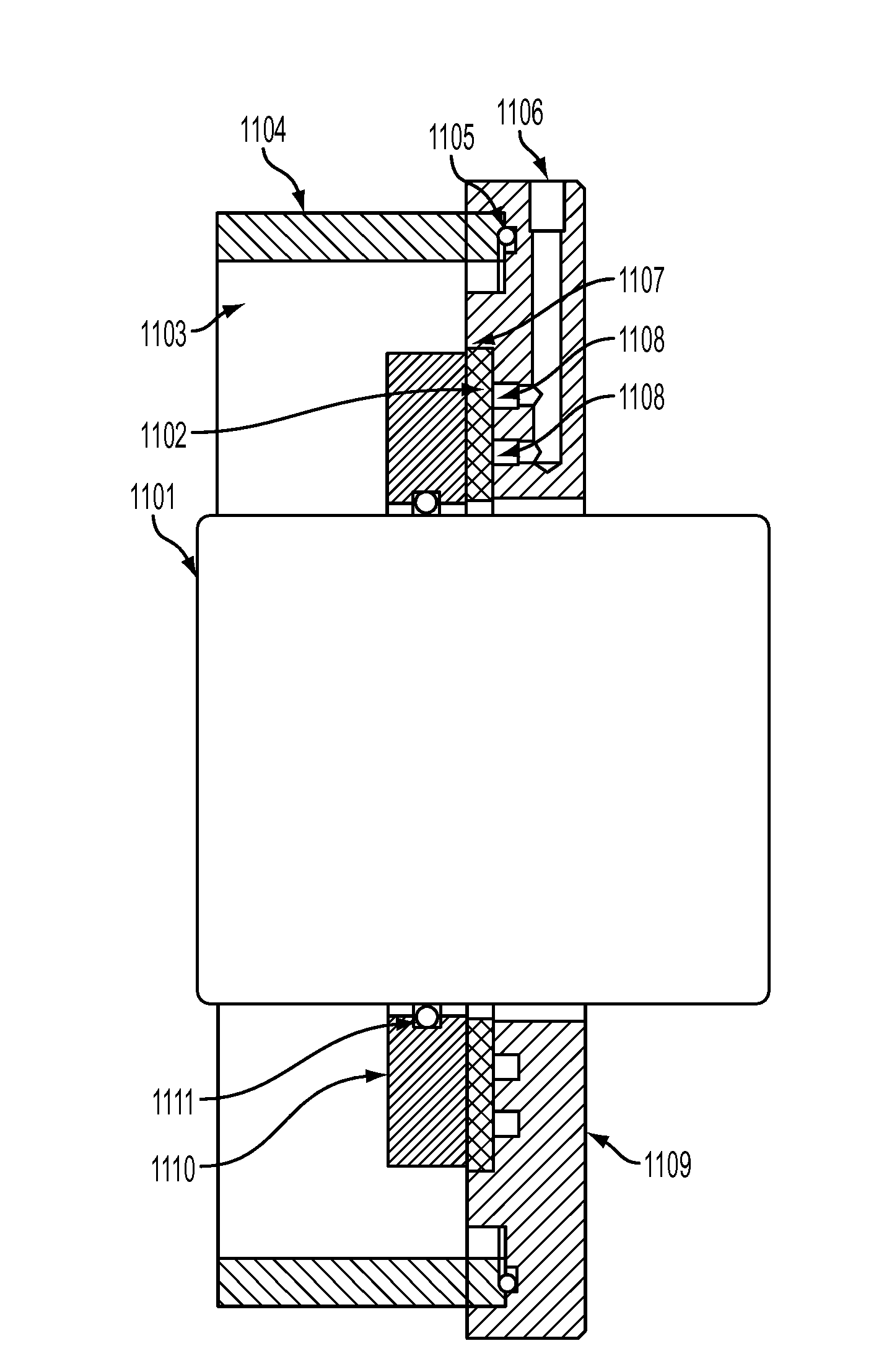
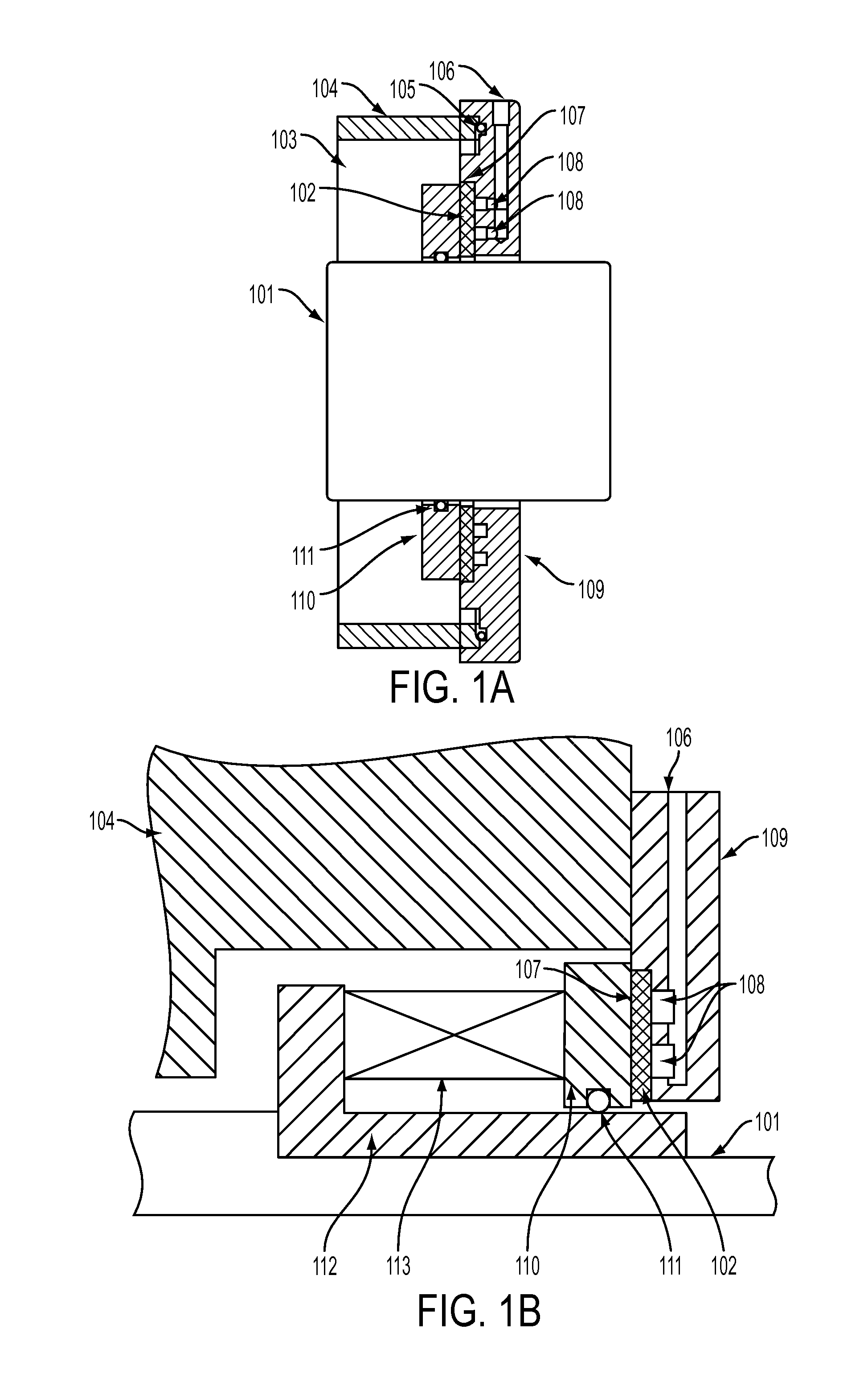
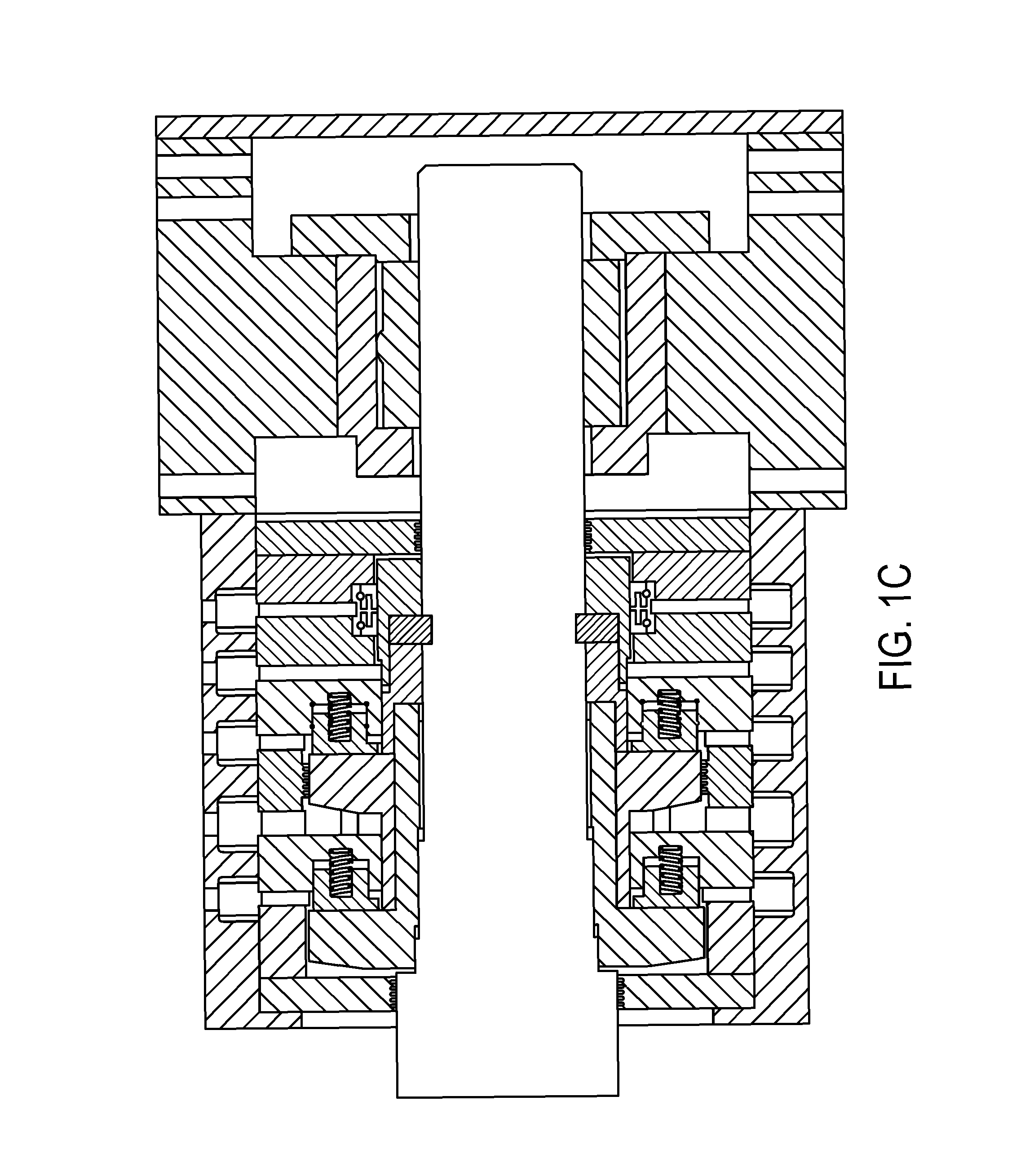
[0055]With reference to FIG. 1A; a shaft 101 which may rotate at high speeds has a runner 110 coupled to it via an O-ring 111 (or another mounting mechanism as detailed in illustration 1B or other arrangements detailed in this specification or known in the art). O-rings provide axial compliance to the runner allowing for self adjustment of the gap between it and the stationary surface and axial displacements of the shaft. If the runner is hard mounted to the shaft some axial compliance should be designed into the stationary components. The runner is free to move radially on the air film. Conventional mechanical face seals as shown in FIG. 1B often have a spring loading mechanism to urge the opposing faces of the seal into contact. This technique is well-known in the art and may be employed to adjust the load o...


PUM


Abstract

In order to effect a seal; a porous material which comprises one side of two opposing surfaces is used to restrict and evenly distribute externally pressurized gas, liquid, steam, etc. between the two surfaces, exerting a force which is opposite the forces from pressure differences or springs trying to close the two faces together and so may create a non contact seal that is more stable and reliable than hydrodynamic seals currently in use.

Description

REFERENCE TO RELATED APPLICATIONS[0001]The present application claims the benefit of U.S. Provisional Application Nos. 61 / 582,674, filed Jan. 3, 2012; 61 / 704,927, filed Sep. 24, 2012; and 61 / 728,595, filed Nov. 20, 2012, whose disclosures are hereby incorporated by reference in their entireties into the present disclosure.FIELD OF THE INVENTION[0002]The present invention is directed to a seal and more particularly to a seal for use in fields such as the following: oil and gas, power generation (including energy storage like compressed air or pumped hydro storage), aero turbines, chemical processing, paper manufacturing, aeration and water purification, gas separation and other process industries. Within these industries is likely that technology will find its way to; pumps, compressors, turbines, generators, motors, turbo expanders, turbo chargers, mixers, and refiners.DESCRIPTION OF RELATED ART[0003]Creating and implementing effective seals for rotating equipment has been an effort...

Claims


Application Information

Patent Timeline
Patent Type & Authority Patents(United States)
IPC IPC(8): F16C33/74F16C32/06F16C11/06F16J15/34
CPCF16C32/0685F16C2202/10F16C32/0618F16C33/748F16C32/0603F16J15/342F16C11/0666F16C32/067F16C32/0677F16C32/0692F16C23/04
Inventor DEVITT, ANDREW
Owner NEW WAY MACHINE COMPONENTS
Why Eureka
Try Eureka