Threaded pipe pulling device

A threaded pipe and pipe material technology, applied in the field of threaded pipe processing, can solve the problems affecting the quality of threaded pipes, poor uniformity of inner diameter of threaded pipes, etc.

Pending Publication Date: 2020-01-07
HANGZHOU SHENSHI ENERGY CONSERVATION TECH
View PDF0 Cites 0 Cited by
  • Summary
  • Abstract
  • Description
  • Claims
  • Application Information

AI Technical Summary

Problems solved by technology

[0006] Therefore, the technical problem to be solved by the present invention is that when the existing pipe-drawing device is provided with a lining core and a core head, there are traces on the inner wall surface of the dra...

Method used


Image

  • Threaded pipe pulling device
  • Threaded pipe pulling device
  • Threaded pipe pulling device

Examples


Embodiment 1

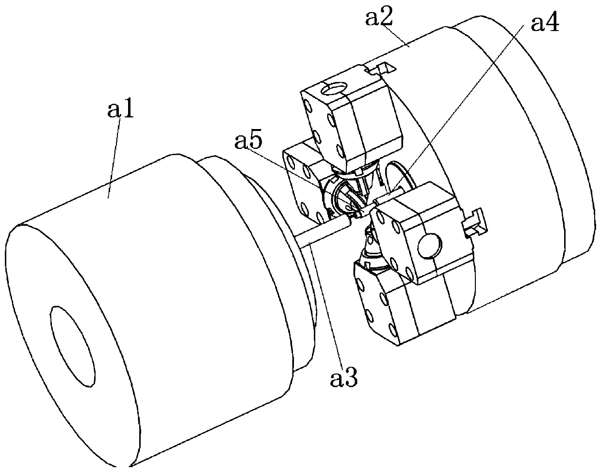
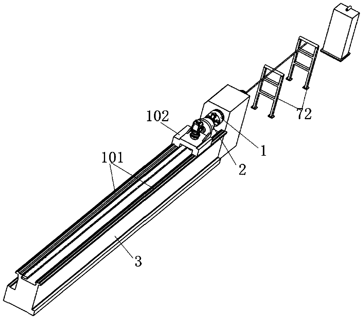
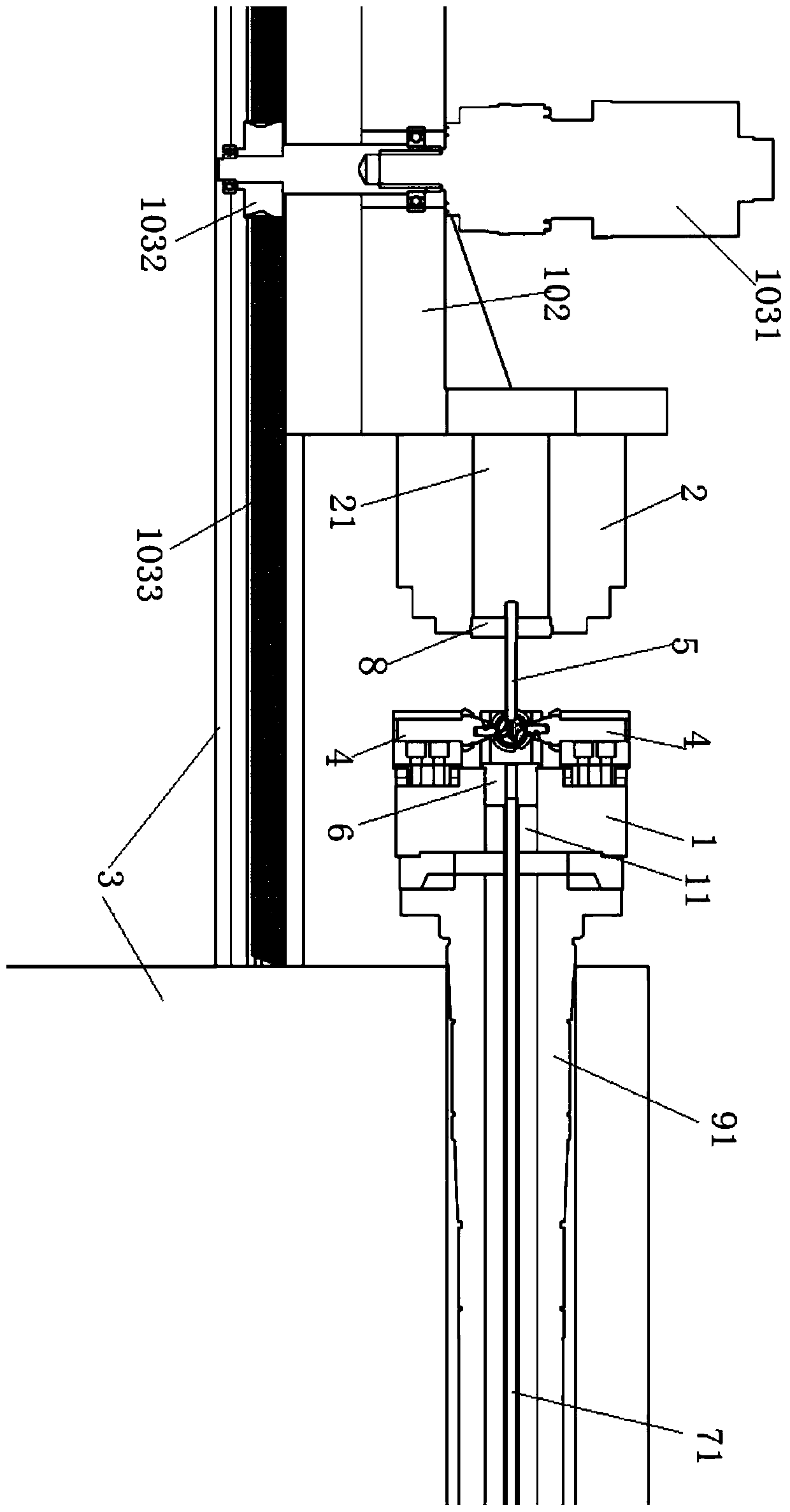
[0050] This embodiment provides a pipe drawing device for a threaded pipe, such as Figure 2 to Figure 9 As shown, it includes a machine tool 3 , a first chuck 1 , a second chuck 2 , a first bushing 6 , a fixing member 5 and several groups of roller assemblies 4 .

[0051] like figure 2 and image 3 As shown, the first chuck 1 and the second chuck 2 are relatively arranged on the machine tool 3, and the second chuck 2 is slidably arranged on the machine tool 3 in the direction of approaching or moving away from the first chuck 1; 1 is rotatably arranged on the machine tool 3 , and a first through hole 11 extending along the sliding direction of the second chuck 2 is provided in the middle of the first chuck 1 . For example, the sliding direction of the second chuck 2 is figure 2 in the left and right directions.

[0052] Several groups of roller assemblies 4 are arranged on the end face of the first chuck 1 facing the second chuck 2 (eg image 3 on the left end of the f...


PUM


Abstract

The invention discloses a threaded pipe pulling device. The threaded pipe pulling device comprises a first chuck, a second chuck, a plurality of groups of pulley components and a fixing part. The circumferential outer walls of pulleys of the pulley components surround to define a chamber body communicating with a first through hole; and the front end, far away from the second chuck, of the fixingpart forms a start position rolling region with the pulleys when extending into the chamber body with the second chuck. The threaded pipe pulling device is not provided with a lining core and a core head which are used for supporting the inner wall of a pipe, so defects such as friction marks or scratches are not formed on the inner wall of the pipe in a pipe pulling process; when the pulleys areused for rolling screw threads at a start position, as the front end of the fixing part extends into the chamber body in order to support the inner wall of the position of start rolling screw threadsof the pipe, the inner diameter of the pipe is prevented from being immediately reduced when the pulley form screw thread position rolling at the start position of the pipe; and thus the inner diameter of a pulled threaded pipe is uniform at different positions.

Description

technical field [0001] The invention relates to the technical field of processing of threaded pipes, in particular to a pipe drawing device for threaded pipes. Background technique [0002] At present, threaded pipes are mostly used in the refrigeration industry, such as threaded pipes used in heat exchangers. Threaded pipes are also gradually applied to food-grade water purifiers. [0003] Most of the existing threaded pipes are pulled out by cored pipes, such as figure 1 As shown, the cored pipe pulling device includes a left chuck a1, a right chuck a2, a chuck a3 mounted on the left chuck, a bushing mounted in the inner hole of the right chuck and one end fixed in the bushing, and the other One end protrudes out of the liner core a4, one end is fixed in the liner core, and the other end protrudes out of the liner core a5; the left end face of the right chuck is provided with a plurality of uniformly arranged around the outer circumference of the core head. A rolling ar...

Claims


Application Information

Patent Timeline
IPC IPC(8): B21D15/06B21D43/00
CPCB21D15/06B21D43/003B21D43/006
Inventor 方洪谭振兴杨立福胡窕窕万观新卢傲杨代坤赵凯凯钱兵保石景祯
Owner HANGZHOU SHENSHI ENERGY CONSERVATION TECH
Why Eureka
Try Eureka